


Instruction Manual
Section Five
NOTE:
If the cutter grinder is equipped with a tilting Wheelhead, this
is simply set to the desired relief angle, as read on the machine scale,
but the toothrest blade end and the center of the cutter are left on
the same plane.
IV. TYPICAL SET-UPS FOR SHARPENING CUTTERS
To give the reader a general idea of the methods commonly employed in the setting
up and sharpening of cutters, the following pages give a number of typical cutters
together with brief descriptions of the grinding procedures employed in each case.
Unless otherwise specified, a cup wheel is assumed for all set-ups.
From the standpoint of design and method of sharpening, cutters may be classified
into two general groups.
A. The first consists of cutters which are sharpened on the periphery or sides, by
grinding the relief angle behind the cutting edge of the tooth. Included in this
group are plain milling cutters (STRAIGHT AND HELICAL TEETH), staggered
tooth cutters, side milling cutters, face milling cutters, end mills, angular cutters,
slitting saws, and reamers.
I.
PLAIN (HELICAL) MILLING CUTTERS
(SEE PAGE 36 FOR ILLUSTRA
TION AND DESCRIPTION OF TYPICAL SET-UP.)
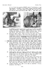
The cutter is mounted on an arbor which is supported between centers and
set sufficiently below the center of the wheel spindle to produce the desired
relief. On tilting Wheelhead cutter grinders, the Wheelhead equiped with
cup wheel, is tilted the desired amount of relief in degrees.
The toothrest must be mounted on the Wheelhead and adjusted so that it
has a complete bearing on the tooth to be ground at the point of grinding
contact. With the cutter held against the toothrest by light hand pressure,
the cutter is traversed across the wheel face, either by moving the table or
by sliding the cutter on a cutter bar. For safety and accuracy, we recom
mend mounting the cutter in a fixed position on an arbor, moving the cutter
relative to the wheel by means of table traverse.
In sharpening any type of plain milling cutter, the greatest difficulty lies
in keeping the peripheral cutting edges radially equal, A cutter out of
truth cuts with a constant pounding action If the wheel wear during the
sharpening operation is equalized, it follows that the cutter is kept cylin
drical. This equalization is achieved by grinding around the entire cutter,
then revolving it 180 degrees, starting anew on a tooth just opposite the
original starting point, taking another light cut all the way around the
cutter This method is repeated, taking light cuts until the cutter has
been sharpened sufficiently.
A straight wheel can also be used for grinding plain cutters. A cup wheel,
however, has the advantage of producing a straight angle or relief back of
the cutting edge. To prevent the opposite side of the cup wheel from
striking the cutter, the Wheelhead should be swivelled slightly from the zero
line in the horizontal plane.
Some tool rooms have found that cutters for use on steel and cast iron
will cut with less chatter and stand up longer between regrinds if they are
first ground cylindrically and then backed off to leave a land from .005" to
.010" wide at the cutting edge.
- 2 6 -
Содержание B2000
Страница 14: ...Instruction Manual Section Three PHOTO 3 4 ...
Страница 24: ...Instruction Manual Section Four PHOTO 9 14 ...


