


Instruction Manual
Section Four
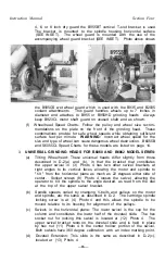
4, 6, or 8 inch dry guard the B955BT vertical T-slot bracket is used
The bracket is mounted to the spindle housing horizontal surface
(SEE INSET). The wheel guard is mounted with the use of the
accompanying wheel guard bracket (SEE INSET). Photo above shows
the B935GS wet wheel guard which is used with the B935 and B2035
coolant attachments. This guard handles wheels up to 7 inches in
diameter and attaches to B955 or B955HD grinding heads Always
keep B923CL motor shaft guard on unused shaft end as shown.
(f) Wheelhead Speed Charts: Follow the pulley and wheel size recom
mendations on the plate on the front of the grinding head. These
combinations provide for safe wheel speeds while obtaining sufficient
surface feet per minute.
WARNING:
Incorrect wheel speed for the
size and type of wheel can cause dangerous wheel destruction. B6055B
and S6055CL Speed Charts for these models are listed on page 14.
3.
UNIVERSAL GRINDING HEADS FOR B6060 AND B6062 MODEL SERIES:
(a) Tilting Wheelhead: These universal heads differ slightly from those
described in D-2(a) and (b), in that the bracket that constitutes
the upper swivel in (3) Photo 4 has two other swivel brackets at
right angles to its vertical faces, allowing the motor and spindle to
" t i l t " from the horizontal plane as much as 22 degrees either side of
center. Socket screws (8) Photo 4 loosen the swivel, allowing the
operator to tilt the spindle to the angle desired, as read from the dial
at the top of the upper swivel bracket.
(b) Spindle speeds, varied by changing V-belts and pulleys on the motor
and spindle, are the same as described in D-2. The cartridge spindle
locking screw is at (4) Photo 4 and this allows the spindle to be
moved relative to its housing for alignment of the pulleys.
(c) Swivels in the horizontal plane: The lower swivel is the cap for the
column and constitutes the lower half of the dovetail slide. The hex
socket nut for locking this swivel is located at (12) Photo 4. The
upper swivel bracket rests on the dovetail slide and is held in place
by hex nut (11) Photo 4 in the center hollow portion of the swivel.
Both swivels have 360 degree calibration with an index marking point,
(d) Dovetail Extension: This slide is the same as described in D-2(c),
located at (13) Photo 4.
—16—
Содержание B2000
Страница 14: ...Instruction Manual Section Three PHOTO 3 4 ...
Страница 24: ...Instruction Manual Section Four PHOTO 9 14 ...


