JYTEK PCIe-6301 Series, Руководство пользователя
Приобретите продукт JYTEK PCIe-6301 Series и получите бесплатное руководство по эксплуатации. Скачайте пользовательское руководство с manualshive.com. Это надежное и мощное устройство, которое поможет вам в повседневных задачах. Установите его с помощью подробной инструкции для оптимальной работы.
Поделиться
Скачать


Отзывы:
Нет отзывов
Похожие инструкции для PCIe-6301 Series

8677 - BladeCenter Rack-mountable - Power...
Бренд: IBM Страницы: 126

DMH25
Бренд: C-Smartlink Страницы: 7

LatticeMico GPIO
Бренд: Lattice Semiconductor Страницы: 28

SuperMac E100
Бренд: UMAX Technologies Страницы: 27

CNPS7000B Series
Бренд: ZALMAN Страницы: 9

DM4610
Бренд: Datacom Страницы: 45

LiveWire
Бренд: LiveAction Страницы: 2

Q7055C1053
Бренд: Honeywell Страницы: 8

Embedded NVR
Бренд: Honeywell Страницы: 2

HN350401 Series
Бренд: Honeywell Страницы: 3

30 Series
Бренд: Honeywell Страницы: 4

Rae SensorRAE 4R+
Бренд: Honeywell Страницы: 2

Mesh Router
Бренд: Honeywell Страницы: 71

FUSION STREAMER
Бренд: Honeywell Страницы: 70
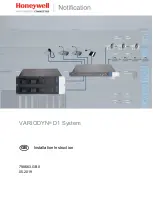
VARIODYN D1
Бренд: Honeywell Страницы: 90

30 Series
Бренд: Honeywell Страницы: 113

TotalPlant LCN
Бренд: Honeywell Страницы: 132

HEN04111
Бренд: Honeywell Страницы: 248


