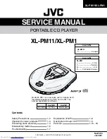
JVC XL-PM1 Скачать руководство пользователя страница 12

XL-PM11/XM-PM1

1-12

1. Block diagram

M11L1644 (IC1644) : DRAM

2. Pin function

Pin No.

3~11, 14~19, 7

5

21

4

20

2, 3,22, 23

1, 12

13, 24

6

Symbol

A0~A10

RAS
CAS

WE

OE

I/O0~I/O3

Vcc
Vss

NC

             Function

Address Input
Row Address : A0~A10
Column Address : A0~A10
Row Address Strobe
Column Address Strobe
Write Enable
Output Enable
Data Input/ Ountput
Power (5V or 3.3V)
Ground
No Connect

11

11

11

11

11

4

4

4

CONTROL

LOGIC

CLOCK

GENERATOR

COLUMN

ADDRESS

BUFFER

REFRESH

CONTROLLER

REFRESH

COUNTER

ROW

ADDRESS

BUFFERS(11)

DATA-IN BUFFER

DATA-OUT

BUFFER

COLUMN

DECODER

SENSE AMPLIFIERS

I/O RATING

2048 x 4

2048 x 2048 x 4

MEMORY

ARRAY

ROW

DECODER

Vdd GENERATOR

2048

2048

WE

RAS
CAS

A0

A1

A2

A3

A4

A5

A6

A7

A8

A9

A10

I/O0

..

I/O3

CE

Vcc
Vss

I/O

I

I
I
I
I

I/O

-

XC6367 (IC6367, 63670) : Regulator

5

4

1

2

3

1. Pin layout

1
2
3
4
5

Pin
No.

Symbol

EXT

GND

CE

VDD

VOUT

Function

2. Pin function

External transistor connection
Ground
Chip enable
Power supply
Voltage output

Содержание XL-PM1

Страница 1: ...roducts Preventing static electricity Disassembly method Troubleshooting Explanation of MP3 Description of major ICs Parts list 1 2 1 3 1 4 1 5 1 7 1 8 1 9 1 13 18 XL PM11 XL PM1 XL PM11 XL PM1 Area Suffix XL PM1 J U S A C Canada B U K E Continental Europe XL PM11 C Canada Area Suffix XL PM11 Gift box XL PM1 Blister pack PACKING Model XL PM11 is an exclusive use for Canada As for the difference be...

Страница 2: ...abinet screw heads headphone jack control shafts etc to be sure the product is safe to operate without danger of electrical shock Do not use a line isolation transformer during this check Plug the AC line cord directly into the AC outlet Using a Leakage Current Tester measure the leakage current from each exposed metal parts of the cabinet particularly any exposed metal part having a return path t...

Страница 3: ...ich prevent emission of radiation when the drawer is open and the safety interlocks have failed or are de feated It is dangerous to defeat the safety switches 5 CAUTION If safety switches malfunction the laser is able to function 6 CAUTION Use of controls adjustments or performance of procedures other than those specified herein may result in hazardous radiation exposure CAUTION Please use enough ...

Страница 4: ...al pickup The tester s internal power source can easily destroy the laser diode 4 Handling the traverse unit optical pickup 1 Do not subject the traverse unit optical pickup to strong shocks as it is a sensitive complex unit 2 Cut off the shorted part of the flexible cable using nippers etc after replacing the optical pickup For specific details refer to the replacement procedure in the text Remov...

Страница 5: ...main board and remove the cabinet door with cabinet middle 1 2 3 4 Disassembly method Removing the cabinet door cabinet middle See Fig 1 to 4 Flexible board is bonded with couple face tapes internally in the cabinet middle Fig 1 Fig 2 The photograph is one of the B and E version Fig 3 The photograph is one of the B and E version A A B B C C C Cabinet door Cabinet door inside Fig 4 FRW000 Main boar...

Страница 6: ...r OCN1 on the main board When reassembling unsolder the short circuit land on the flexible board after connecting the flexible board Flexible board is bonded with a couple face tape on the bottom cabinet Prior to performing the following procedure remove the cabinet door and cabinet middle Remove the eight screws E attaching the metal cover Peel off the warning label if necessary Remove the metal ...

Страница 7: ...s Yes Yes Yes No No No No No No No No No No No No No No No No No No No TOC READ PLAY CHECK ALL KEY FUNCTION CHECK ASP 9226 CIRCUIT CHECK VOLTAGE PIN No 24 of IC9226 DC LEVEL CHECK VOLTAGE PIN No 1 2 of CON2 DC LEVEL CHECK VOLTAGE PIN No 2 3 of CON1 0 5V 3V CHECK VOLTAGE CONNECTOR PIN of Q301 2V CHECK VOLTAGE PIN No 4 5 of CON2 DC LEVEL CHECK DRIVE IC 6508 CIRCUIT CHECK DRIVE IC 6508 REPLACE MAIN P...

Страница 8: ...sound which is masked 2 MPEG 1Audio is divided into three layers Layer 1 Layer 2 and Layer 3 The higher the Layer number the higher the compression rate and the better the sound quality 32 kHz 44 1 kHz and 48 kHz sampling rates are supported Monaural and 2 channel stereo can be compressed to 32 448 kbps with Layer 1 32 384 kbps with Layer 2 and 32 320kbps with Layer 3 The following is a summary of...

Страница 9: ...l CH2 Control signal input terminal Reference voltage input terminal Pin No 17 18 19 20 21 22 23 24 25 26 27 28 29 30 31 32 Symbol VCC VG IN3 CN3 POWGND3 OUT_3F POWVCC3 OUT_3R POWGND34 OUT_4R POWVCC4 OUT_4F CN4 IN4 POWGND4 CLK Function Control circuit power supply Pre drive circuit power supply CH3 Control signal input terminal CH3 Feedback filter terminal Ground for power block CH3 Non inverted o...

Страница 10: ...tor output Digital Power Test input EFM signal input CLV Servo locking status output LPF time constant control of the spindle servo error signal ON OFF control signal for spindle servo Phase control output for Spindle Motor drive Speed control output for Spindle Motor drive Word clock output X1 88 2KHz X2 176 4KHz Digital Power Various Test input Write base clock output The Lock status output of f...

Страница 11: ...D1 WE RAS D2 D3 CAS0 CAS1 AD10 AD8 AD7 AD6 AD5 AD4 AD9 AD0 AD1 AD2 AD3 VSSD4 I O I O I O I O I O O O I O I O O O O O O O O O O O O O Function Read base clock output Monitoring signal output Digital Ground Digital Power DRAM data Input Output 0 DRAM data Input Output 1 DRAM Write Enable output active Low DRAM Row Address Selection output active Low DRAM data Input Output 2 DRAM data Input Output 3 ...

Страница 12: ...11 11 11 11 11 4 4 4 CONTROL LOGIC CLOCK GENERATOR COLUMN ADDRESS BUFFER REFRESH CONTROLLER REFRESH COUNTER ROW ADDRESS BUFFERS 11 DATA IN BUFFER DATA OUT BUFFER COLUMN DECODER SENSE AMPLIFIERS I O RATING 2048 x 4 2048 x 2048 x 4 MEMORY ARRAY ROW DECODER Vdd GENERATOR 2048 2048 WE RAS CAS A0 A1 A2 A3 A4 A5 A6 A7 A8 A9 A10 I O0 I O3 CE Vcc Vss I O I I I I I I O XC6367 IC6367 63670 Regulator 5 4 1 2...

Страница 13: ...d battery See page 1 16 Knob hold See page 1 16 Holder battery See page 1 16 Integrated decomposition chart Cabinet door assembly See page 1 14 Cabinet middle assembly See page 1 14 Cabinet bottom assembly See page 1 16 Block No M M M 1 Main board assembly See page 1 15 ...

Страница 14: ...CABINET DOOR Description WITH FRONT BOARD Cabinet middle assembly Parts number AH64 01528A Parts name CABINET MIDDLE Description WITH RIBBON Area suffix ALL Parts number AH64 01527B Parts name CABINET DOOR Description WITH FRONT BOARD Area suffix C Area suffix ALL XL PM11C XL PM1 ...

Страница 15: ...Parts name MAIN BOARD ASSY VR ROTARY SWITCH SLIDE SWITCH DETECTOR JACK DC POWER JACK LINE OUT JACK PHONE BRACKET BATTERY P SPRING BATTERY BRACKET CHARGER CONNECTOR SOCKET Description PCB MAIN VOLUME HOLD S W DOOR S W Area suffix ALL ALL ALL ALL ALL ALL ALL ALL ALL ALL ALL 3 1 4 7 5 6 9 8 10 11 CD mechanism assembly Parts number AH59 00968A Parts name CD MECHANISM ASSY Description MECH RUBBER CD Ar...

Страница 16: ...NET MIDDLE INSIDE BOTTOM SIDE Area suffix B E J C E B B E J C Parts number AH64 01021A AH61 00734A AH64 01029A Parts name LID BATTRY HOLDER BATTERY KNOB HOLD Description BATTERY COVER Area suffix ALL ALL ALL Labels Cabinet bottom assembly Parts number AH64 01529A Parts name CABINET BOTTOM Description WITH BATTERY COVER Area suffix ALL Parts number AH68 00875C Parts name LABEL RATING Description BO...

Страница 17: ...No M M M 5 Blister XL PM1J XL PM1C No do after sales service of blister pack packing Parts name PE BAG PAD CUSHION PACKING CASE PACKING CASE LABEL GIFT BOX Parts number AH69 00359A AH69 00538A AH69 00538B AH69 00538C AH68 00930A Description HDPE SW 1 SW 1 SW 1 ART PAPER Q ty 2 1 1 1 1 Area ALL 11C B E 11C B E 11C B E Item P1 P2 P3 P4 Parts list Packing Block No M3MM ...

Страница 18: ...68 00944C AH68 00944E AH68 00944D AH64 01082A AH30 00016A AH30 00015A AH44 00022A AH44 00021A AH44 00020A BT 51626 1 BT 52004 1 BT 54008 2 BT 20071B BT 20044G E43486 340B BT 51020 2 Description EN FR EN SP NL GE IT FR SW FI DA EN ASSY OVER HEAD INNER EAR AA R4510 AA R4511 AA R4512 Q ty 1 1 1 1 1 1 1 1 1 1 1 1 1 1 1 1 Area C 11C E J B ALL J C 11C B E J C 11C E B J C B E C J B J Item A1 A2 A3 A4 A5 ...

Страница 19: ...XL PM11 XM PM1 1 19 M E M O ...

Страница 20: ...200107 V VICTOR COMPANY OF JAPAN LIMITED PERSONAL MOBILE NETWORK BUSINESS UNIT 10 1 1chome Ohwatari machi Maebashi city 371 8543 Japan No 21018 XL PM11 XL PM1 ...

Страница 21: ...XL PM11 XL PM1 2 1 1 2 3 4 5 A B C D Block diagram ...

Страница 22: ...A B C D E F G 2 2 XL PM11 XL PM1 andard schematic diagram CD signal ASP 16MDRAM DSP ESP MP3 DECODER MICROPROCESSOR M DRIVER HP AMP ...

Страница 23: ...factory 1 Page Parts No Parts Name FOB New Parts Itg Rsn Note D G The following parts have been changed Please note these new parts in your service manual We suggest that you order the parts concerned as apares Parts identified by the symbol are critical for safety Replace only with specified part numbers 3722 001493 Jack Line out 1 15 ATTACHMENT NONE COMPONENT PWBLAYOUT SCHEMATIC DIAGRAM ADJUSTME...

Отзывы: