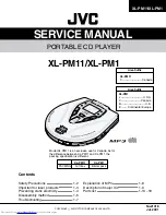
XL-PM11/XM-PM1
1-11
3. Block diagram
DPLL
CLV
Servo
Timing
Generator
Micom
Interface
Subcode
Out
EFM
Demodulator
ECC
16K
SRAM
Address
Generator
Interpolator
Digital
Out
I/O
Interface
Encoder
Decoder
DRAM
Interface
Digital
Filter
1-bit
DAC
PWM
LPF
SQCK
SBCK
S0S1
SQDT
SBDT
C2HO
DAIX
VHALF
VREF
LCHOUT
RCHOUT
AD9 - AD0
D3 D0
CAS1- CAS0
RAS
WE
JITB
VCO1LP
VCO2LP
EFMI
LOCK
SMLT
SMON
SMDP
SMDS
WDCK
TESIV
WFCK
RFCK
C4M
XIN
ISIAI
MLL
MDAL
MCK
MUTE
Pin No.
53
54~59
60
61
62
63
64
65
66
67
68
69
70
71
72
73
74
75
76
77
78
79
80
Symbol
RFCK
MNT0~5
VSSD3
VDDD4
D0
D1
WE
RAS
D2
D3
CAS0
CAS1(AD10)
AD8
AD7
AD6
AD5
AD4
AD9
AD0
AD1
AD2
AD3
VSSD4
I/O
I/O
I/O
-
-
I/O
I/O
O
O
I/O
I/O
O
O
O
O
O
O
O
O
O
O
O
O
-
Function
Read base clock output
Monitoring signal output
Digital Ground
Digital Power
DRAM data Input/Output 0
DRAM data Input/Output 1
DRAM Write Enable output (active Low)
DRAM Row Address Selection output (active Low)
DRAM data Input/Output 2
DRAM data Input/Output 3
DRAM Column Address Selection output 0 (active Low)
DRAM Column Address Selection output 1 (active Low)
DRAM Address output 8
DRAM Address output 7
DRAM Address output 6
DRAM Address output 5
DRAM Address output 4
DRAM Address output 9
DRAM Address output 0
DRAM Address output 1
DRAM Address output 2
DRAM Address output 3
Digital Ground
2. Pin function
(2/2)
Содержание XL-PM1
Страница 19: ...XL PM11 XM PM1 1 19 M E M O ...
Страница 21: ...XL PM11 XL PM1 2 1 1 2 3 4 5 A B C D Block diagram ...


