(No.22019)1-19
SECTION 4
ADJUSTMENT
4.1
Adjustment of idling current
Attention:
This adjustment does not obtain a correct adjustment value immediately after the amplifier is used (state that an internal temperature
has risen).
Please adjust immediately after using the amplifier after turning off the power supply of the amplifier and falling an internal temper-
ature.
Adjustment method
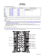
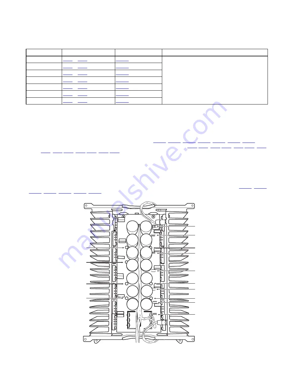
(1) Prior to turning the power ON, fully turn the adjusting resistor (
VR701
,
VR702
,
VR751
,
VR752
,
VR771
,
VR772
,
VR801
) coun-
terclockwise direction and connect the DC voltmeter to the measuring terminal (
B901
-
B902
,
B903
-
B904
,
B905
-
B906
,
B907
-
B908
,
B909
-
B910
,
B911
-
B912
,
B913
-
B914
).
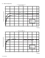
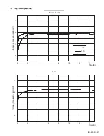
(2) Adjust the resistor so that the measured value becomes 2.0mV just after the power supply is turned on.
(3) Adjust the resistor so that the measured value becomes 2.5mV more than 60 seconds after the power supply is turned on.
(4) After stability is 1.0-4.0mV.
Refer to following page "Idling Current graph".
* It is not abnormal though the idling current might not become 0mA even if it is finished to turn variable resistance (
VR701
,
VR702
,
VR751
,
VR752
,
VR771
,
VR772
,
VR801
) in the direction of counterclockwise.
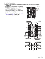
Measuring point
Alignment point
Measuring condition
Lch
B903
&
B904
VR701
No load and No signal.Rated line voltage
SURROUND : OFF
Room temperature : 20~25ºC
Rch
B911
&
B912
VR751
Cch
B907
&
B908
VR801
SLch
B907
&
B908
VR771
SRch
B909
&
B910
VR772
SBLch
B901
&
B902
VR702
SBRch
B913
&
B914
VR752
B901, B902 (SBLch)
B903, B904 (Lch)
B905, B906 (SLch)
B907, B908 (Cch)
B909, B910 (SRch)
B911, B912 (Rch)
B913, B914 (SBRch)
VR701 (Lch)
VR801 (Cch)
VR771 (SLch)
VR702 (SBLch)
VR772 (SRch)
VR752 (SBRch)
VR751 (Rch)

