1-8 (No.22019)
3.1.5
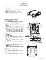
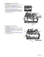
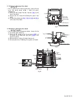
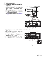
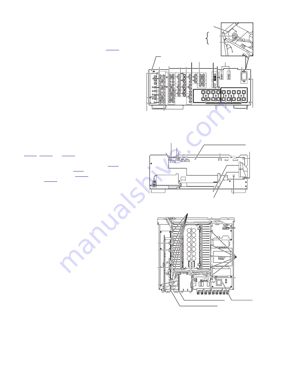
Removing the audio 7.1ch in board
(See Fig.2 and 4)
• Prior to performing the following procedure, remove the top
cover.
(1) Cut off the tie band 2 & 3 fixing the harness.
(2) Disconnect the harness from the connector
CN201
on the
audio signal 1 board.
(3) Remove the two screws
E''''
attaching the audio 7.1ch in
board to the rear panel.
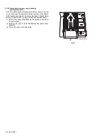
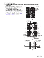
3.1.6
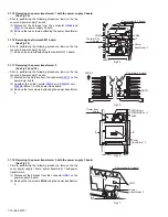
Removing the rear panel
(See Fig.4)
• Prior to performing the following procedure, remove the top
cover.
(1) Unsolder the two solder parts on the AC inlet.
(2) Remove the thirty-eight screws
E
&
E'
&
E''
&
E'''
&
E''''
attaching each board to the rear panel.
(3) Remove the thirteen screws
F
attaching the rear panel on
the back of the body and bottom.
Fig.4
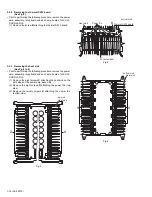
3.1.7
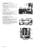
Removing the system control board
(See Fig.5 and 6)
• Prior to performing the following procedure, remove the top
cover and front panel assembly.
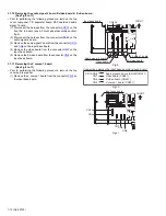
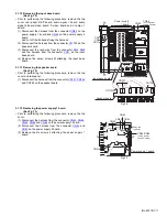
(1) Disconnect the card wires and harness from the connector
CN963
,
CN964
and
CN981
on the system control board.
(2) Cut off the tie bands fixing the harness.
(3) Disconnect the harness from the connector
CN45
on the
power supply 2 board and
CN25
on the power/ fuse board.
(4) Disconnect the connector
CN324
on the audio signal 2
board and
CN234
on the audio signal 1 board.
(5) Remove the three plastic rivet.
Fig.5
Fig.6
E
F
E'''
E
F
F
F
F
Rear panel
Red
Black
E
E
E''
E''''
E'
E
E
F
Solder part
AC inlet
CN963
CN981
CN971
CN977
CN983
CN964
CN985
System control board
Plastic rivet
Plastic rivet
CN324
CN25
CN234
CN224
CN45
(on power
supply 2
board
)
Power/ fuse
board
Audio signal 1 board
Audio signal 2 board
CN203
Tie band
Tie band

