1-7
RX-7000RBK
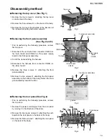
Prior to performing the following procedure, remove
the top cover and the front panel.
Remove the one nut attaching the headphone jack of
the power supply board on the front side of the body.
Disconnect the relay board 1, 2 and 3 from the
power supply board and the main board respectively.
Disconnect the harness connected to connector
CN55 and CN56 on the power transformer board (If
necessary, cut off the two tie bands fixing the
harness on the side of the chassis base).
Remove the four screws O attaching the power
supply board and pull out the power supply board
from the front bracket backward.
Unsolder the three harnesses connected to the
power supply board.
1.
2.
3.
4.
5.
Removing the power supply board
(See Fig.17 and 18)
Prior to performing the following procedure, remove
the top cover and the front panel assembly.
Pull out the volume knob on the front side of the front
panel and remove the nut attaching the system
control board.
Remove the six screws P attaching the system
control board on the back of the front panel and
disconnect the harness from connector CN422 on
the system control board.
Disconnect the harness from connector CN430 on
the power switch board.
Remove the five screws Q attaching the power
switch board.
1.
2.
3.
4.
Removing the system control board /
power switch board (See Fig.19 to 20)
Fig.17
Fig.18
Fig.19
Fig.20
Power supply board
Nut
Headphone jack
Tie band
Tie band
Relay board 1
Relay board 2
Relay board 3
Power transformer
Solder
O
O
O
Headphone jack
Solder
Power supply board
Front panel
Nut
Volume knob
System control board
Power switch board
Front panel assembly
P
Q
CN430
CN422
Q
P
P
CN55
CN56
Содержание RX-7000RBK
Страница 26: ...1 26 RX 7000RBK MEMO ...
Страница 41: ...2 15 RX 7000RBK I H A B C D E F G 1 2 3 4 5 6 FL Display System control board FL Display System control board ...
Страница 44: ...RX 7000RBK 3 2 MEMO ...
Страница 126: ...VICTOR COMPANY OF JAPAN LIMITED EN GE FR NL SP IT J VC 0400HIMMDWJEIN RX 7000R E COVER f 00 4 25 0 01 PM 2 ...


