


KD-LX10/KD-LX30
2-5
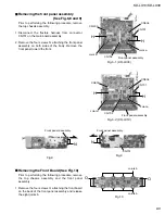
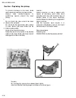
Prior to performing the following procedure, remove
the top chassis assembly, the front panel assembly
and the lifer unit.
Remove the screws S attaching the right and left
brackets which fix gears on both sides of the
operation assembly.
Remove the springs 5 and 6 from the operation
assembly.
Disconnect the card wire from connector CN702 on
the main board and remove the operation assembly.
1.
2.
3.
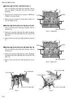
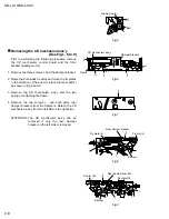
Removing the operation assembly
(See Fig.14 to 17)
when reassembling, correctly engage
the switch S561 and S562 on the main
board and the right gear with the part e
of the operation assembly.
ATTENTION:
Fig.14
Fig.15
Fig.16
Fig.17
S
Spring 6
CN702
Operation assembly
Spring 5
S
Operation assembly e
S652
S651
Operation assembly
e
Operation assembly e
S652
S651
Bracket (R)
Bracket (L)
Bracket (R)
Содержание KD-LX10
Страница 15: ...KD LX10 KD LX30 2 13 ...
Страница 42: ...KD LX10 KD LX30 2 40 ...
Страница 46: ...CD SIGNAL KD LX10J CD servo LCD control section ...
Страница 47: ...KD LX30J Main amp section AUX SIGNAL FRONT SIGNAL REAR SIGNAL TUNER SIGNAL CD SIGNAL CD CHANGER SIGNAL ...
Страница 48: ...KD LX30J CD servo LCD control section CD SIGNAL ...


