


KD-LX10/KD-LX30
2-1
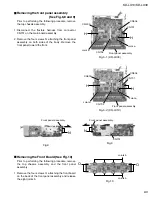
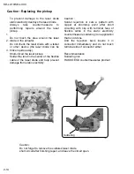
Remove the two screws A attaching the bottom
cover to the top chassis on the bottom of the body.
Remove the two screws B attaching the top chassis
on both sides of the body.
Remove the two screws C and the two screw D
attaching the heat sink on the left side of the body.
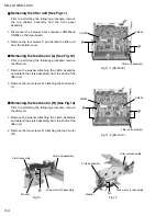
Remove the two screws E and the screw F on the
back of the body.
Remove the two screws G on the upper side of the
body.
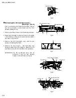
Move the top chassis upward and disconnect the CD
mechanism connector from the main board
connector by pulling it. Remove the top chassis from
the body.
1.
2.
3.
4.
5.
6.
Disassembly method
Removing the top chassis
(See Fig.1 to 5)
Fig.1
Fig.2
Fig.3
Fig.4-1 (KD-LX30)
Fig.4-2 (KD-LX10)
Fig.5
Bottom cover
A
A
B
Top chassis
Top chassis
Heat sink
C
D
B
E
F
E
F
Top chassis
G
G
Содержание KD-LX10
Страница 15: ...KD LX10 KD LX30 2 13 ...
Страница 42: ...KD LX10 KD LX30 2 40 ...
Страница 46: ...CD SIGNAL KD LX10J CD servo LCD control section ...
Страница 47: ...KD LX30J Main amp section AUX SIGNAL FRONT SIGNAL REAR SIGNAL TUNER SIGNAL CD SIGNAL CD CHANGER SIGNAL ...
Страница 48: ...KD LX30J CD servo LCD control section CD SIGNAL ...


