


KD-LX10/KD-LX30
2-8
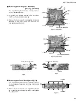
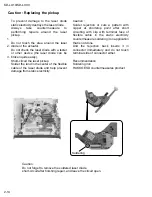
Fig.5
Fig.6
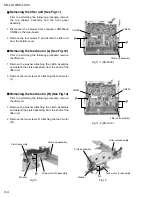
Fig.7
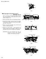
Fig.8
Fig.9
Rear damper bracket
Fix arm (R)
Damper
I
I
Damper bracket
CD mechanism ass’y
Flame
m
m
I
I
Fix plate (L)
l
l
Rear damper bracket
Fix arm (L)
Damper
J
Fix plate(R)
J
l
l
H
Loading motor
Belt
Prior to performing the following procedure, remove
the CD mechanism control board and the front
bracket (loading motor).
Remove the three screws I and the damper bracket.
Raise the both sides fix arms and move the fix plates
in the direction of the arrow to place the four shafts l
as shown in Fig.8 and 9.
Remove the CD mechanism ass’y and the two
springs m attaching the flame.
Remove the two screws J and both sides rear
damper brackets from the dampers. Detach the CD
mechanism ass’y from the left side to the right side.
1.
2.
3.
4.
Removing the CD mechanism ass’y
(See Fig.1, 6 to 9)
The CD mechanism ass’y can be
removed if only the rear damper
bracket on the left side is removed.
ATTENTION:
Содержание KD-LX10
Страница 15: ...KD LX10 KD LX30 2 13 ...
Страница 42: ...KD LX10 KD LX30 2 40 ...
Страница 46: ...CD SIGNAL KD LX10J CD servo LCD control section ...
Страница 47: ...KD LX30J Main amp section AUX SIGNAL FRONT SIGNAL REAR SIGNAL TUNER SIGNAL CD SIGNAL CD CHANGER SIGNAL ...
Страница 48: ...KD LX30J CD servo LCD control section CD SIGNAL ...


