(No.YD070)1-23
4.3.3 Previous Preparation for Deck Adjustment
(Preparation to load the VCR (VCP) with cassette tape not inserted)
(1) Take the power cord from the consent.
(2) Separate the top cover and the plate assembly top.
(3) Insert the power cord into again.
(4) Turn the VCR (VCP) on and load the cassette while push-
ing the lever stopper of the holder assembly CST back-
ward. In this case, clog both holes on the housing rail part
of chassis to prevent detection of the end sensor.
If doing so, proceeding to the stop mode is done. In this status,
input signals of all modes can be received. However, operation
of the Rewind and the Review is impossible since the take-up
reel remains at stop status and so cannot detect the reel pulse
(however, possible for several seconds).
4.3.4 Torque Measuring
Purpose of Measuring : To measure and check the reel torque on the take-up part and the
supply part that performs basic operation of the VCR (VCP) for
smoothly forwarding the tape.
Measure and check followings when the tape is not smoothly
wound or the tape velocity is abnormally proceeded:
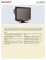
Adhere the torque gauge adaptor to the torque gauge for measuring the value.
Fig. C-3-2
Fig. C-3-1
Torque Gauge
Torque Gauge
Adaptor
Reel Table
Item
Fast forward Torque
Rewind Torque
Play Take-Up Torque
Review Torque
Fast Forward
Rewind
Play
Review
Torque Gauge
Torque Gauge
Cassette Torque Meter
Cassette Torque Meter
Take-Up Reel
Supply Reel
Take-Up Reel
Supply Reel
More than 400g cm
More than 400g cm
40~100g cm
40~210g cm
Mode
Instruments
Reel Measured
Measuring Value
Cassette Torque Meter
Torque Gauge (600g.cm ATG)
VCR (VCP) status
Measuring method
Fixtures and tools used
Torque Gauge
(600 g.cm ATG)
Torque Gauge Adaptor
Cassette Torque Meter
Play (FF) or Review
(REW) Mode
Try to operate the VCR (VCP) per mode with the
tape not inserted (See 4.3.3 Prior Preparation for
Deck Adjustment).
Measure after adhering and fixing the torque
gauge adaptor to the torque gauge (Fig. C-3-1)
Read scale of the supply or take-up part of the
cassette torque meter (Fig. C-3-2).
NOTE
SRK
VIDEO
CASSETTE
TORQUE
METER
VHT-303
S
R
K
-
V
H T
- S
SR
K - V H T - T
300
250
200
150
50
0
300
250
200
150
50
0
Содержание HR-XV45SEF
Страница 9: ... No YD070 1 9 SECTION 3 DISASSEMBLY This service manual does not describe DISASSEMBLY ...
Страница 69: ... No YD070 1 69 F FE RFL FIG 7 2 DVD F FE RFL FIG 7 3 CD ...
Страница 70: ...1 70 No YD070 5 4 8 FOCUS ON WAVEFORM F FE RFL FIG 7 4 CD FIG 8 1 DVD FE FOSO F F ...
Страница 74: ...1 74 No YD070 5 4 13 MT1389 AUDIO OUTPUT TO AUDIO DAC 2 COMPOSITE VIDEO SIGNAL FIG 12 2 FIG 13 1 ...
Страница 75: ... No YD070 1 75 5 4 14 AUDIO OUTPUT FROM AUDIO DAC FIG 14 1 ...
Страница 77: ...INSTRUCTIONS DVD PLAYER VIDEO CASSETTE RECORDER PAL HR XV45SEK EN ...
Страница 119: ... 2005 Victor Company of Japan Limited Printed in Indonesia EK P NO 3834RV0038A HR XV45SEK EN ...
Страница 126: ...A 1 2 3 4 5 B C D E F G EE MODE VIDEO TU MODE AUDIO TUNER IF CIRCUIT DIAGRAM SHEET 4 2 11 2 12 ...
Страница 128: ...A 1 2 3 4 5 B C D E F G SCART JACK CIRCUIT DIAGRAM SHEET 6 2 15 2 16 ...
Страница 129: ...A 1 2 3 4 5 B C D E F G DVD RF DSP SERVO CIRCUIT DIAGRAM SHEET 7 2 17 2 18 ...
Страница 130: ...A 1 2 3 4 5 B C D E F G DVD AV JACK CIRCUIT DIAGRAM SHEET 8 2 19 2 20 ...
Страница 131: ...A 1 2 3 4 5 B C D E F G DVD SYSTEM CIRCUIT DIAGRAM SHEET 9 2 21 2 22 ...
Страница 132: ...PRINTED CIRCUIT DIAGRAMS LOCATION GUIDE VCR MAIN CIRCUIT BOARD TOP SIDE 2 23 2 24 ...
Страница 133: ...LOCATION GUIDE BOTTOM SIDE VCR MAIN CIRCUIT BOARD 2 25 2 26 ...
Страница 134: ...LOCATION GUIDE LOCATION GUIDE POWER BOARD KEY BOARD 2 27 2 28 ...
Страница 152: ... No YD070 3 5 052 517 061 056 518 052A 055 410 077 076 078 060 051 064 A11 A12 023 080 058 Back side ...