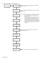
(No.MB306)1-17
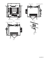
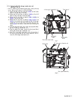
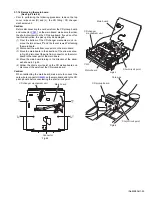
3.1.8 Removing the POWER switch board / CD switch board
(See Fig.25, 26)
• Prior to performing the following procedure, remove the front
panel assembly.
(1) Remove the two screws
P
and the three screws
Q
attach-
ing the bracket.
(2) Remove the screws
R
attaching the POWER switch board.
(3) Remove the screw
T
attaching the CD switch board.
Fig.25
Fig.26
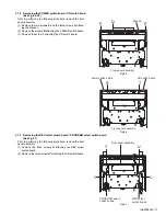
3.1.9 Removing the REC select switch board / PROGRAM select switch board
(See Fig.27)
• Prior to performing the following procedure, remove the front
panel assembly.
(1) Remove the three screws
U
attaching the REC select
switch board.
(2) Remove the three screws
Y
attaching the CD switch board.
Fig.27
P
Q
P
Front panel assembly
Bracket
R
T
CD switch board
Power switch board
Front panel assembly
Y
Y
PROGRAM select
switch boaed
REC select
switch boaed
U
U
Front panel assembly
Содержание CA-MXKB22
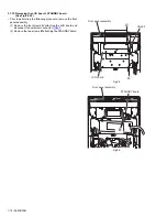
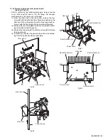
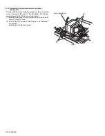
Страница 16: ...1 16 No MB306 Fig 23 Fig 24 f Front panel assembly N N Front panel assembly ...
Страница 33: ... No MB306 1 33 SECTION 5 TROUBLESHOOTING This service manual does not describe TROUBLESHOOTING ...
Страница 42: ...2 6 TC9462F U401 TO PICK UP TO CD DECK CD section MX KB22 TO MCU ...
Страница 43: ...2 7 CD section MX KB1 TC9462F U401 TOMCU TO MCU ...
Страница 45: ...2 9 PROTECT CIRCUIT Power section MX KB22 AMP STK402 050 METAL FILM RESISTORS NONFLAME FUSIBLE AC PLUG ...
Страница 46: ...2 10 PROTECT CIRCUIT Power section MX KB1 AMP STK402 050 METAL FILM RESISTORS NONFLAME FUSIBLE AC PLUG ...
Страница 52: ...2 16 Main board forward side reverse side Printed circuit boards ...
Страница 53: ...2 17 Display board forward side reverse side Power board forward side reverse side ...
Страница 55: ...2 19 Speaker jack board Headphone board forward side reverse side ...
Страница 71: ...3 15 MEMO ...


