


Jupiter Instruments
_____________________________________________________________________________________
JI-300
11
9/9/07
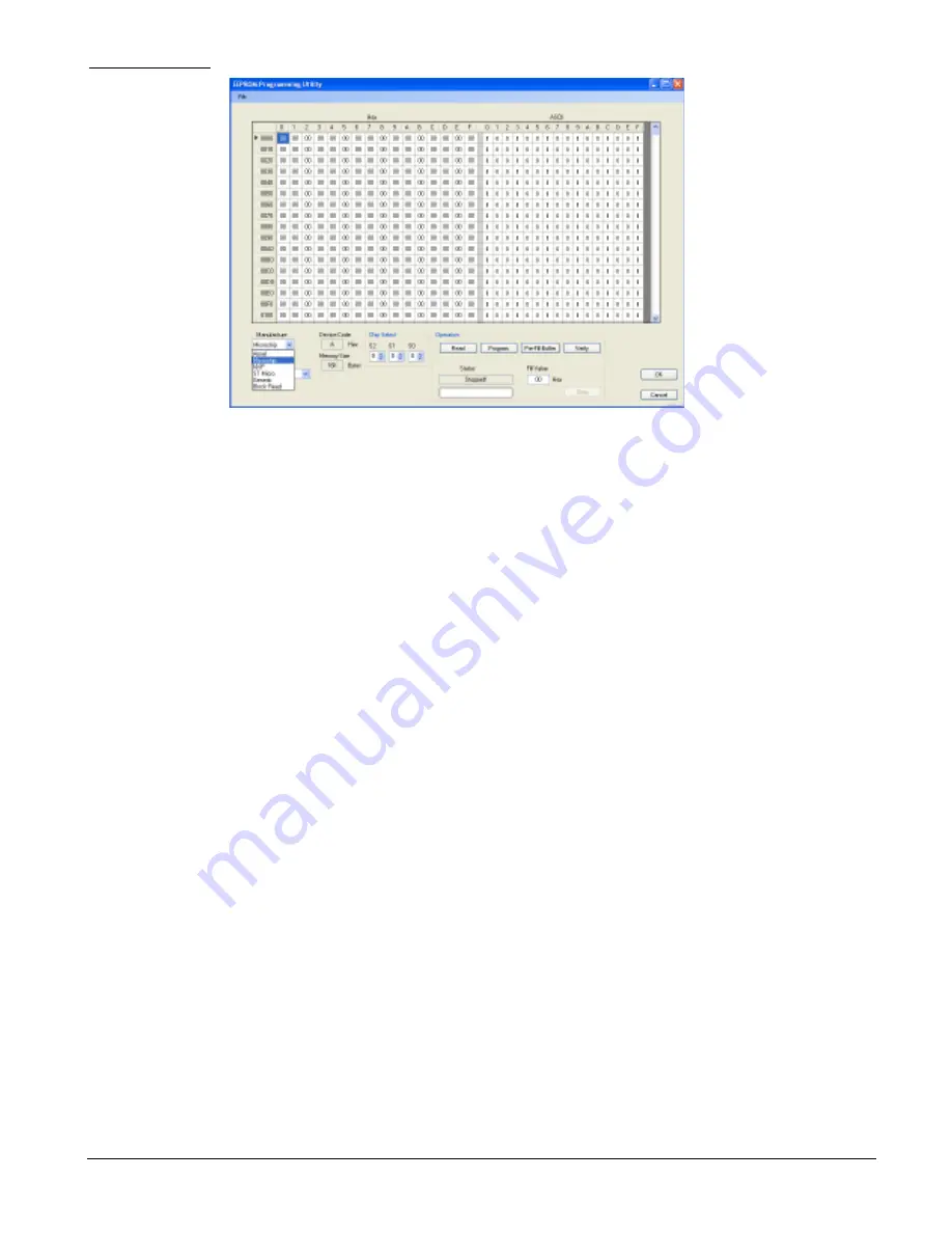
Figure 6.
EEPROM Programming Utility window
4. Enter the manufacture and device type for the target EEPROM. For this exercise, text box
data is enter as follows:
•
Manufacture:
ST Micro
•
Device:
M24C04
These two text boxes are located at the lower left-hand side of the Programming Utility
window.
5. Enter EEPROM chip select data.
•
CS2:
0
•
CS1:
0
•
CS0:
N/A
6. Now, verify device settings by successfully reading the EEPROM. This is accomplished by
clicking the
Read
button in the Operation group. A read time for this device is approximately
5 seconds and a successfully operation will display “Done!” in the status text box.
7. Next, fill the
Buffer
with ASCII “space” characters by entering 20h in the
Fill Value
text
box and then clicking the
Pre-Fill Buffer
button.
8. Verify that the
Buffer
contains the HEX value 20h.
9. Type the word “Top” beginning at address 000h in the ASCII section of the
Buffer
.
10. Type the word “Bottom” beginning at address 1f0h in the ASCII section of the
Buffer
.
11. Program the EEPROM by clicking the
Program
button.
12. A message box will appear asking, “Are you sure you want to program this device?” Click
yes. Programming begins.
13. After approximately 5 to 10 seconds programming will end and “Done Programming!” will
be displayed in status text box.