background image

Removing a TX Matrix PC Card

The PC Card is inserted into the slot labeled

PC CARD

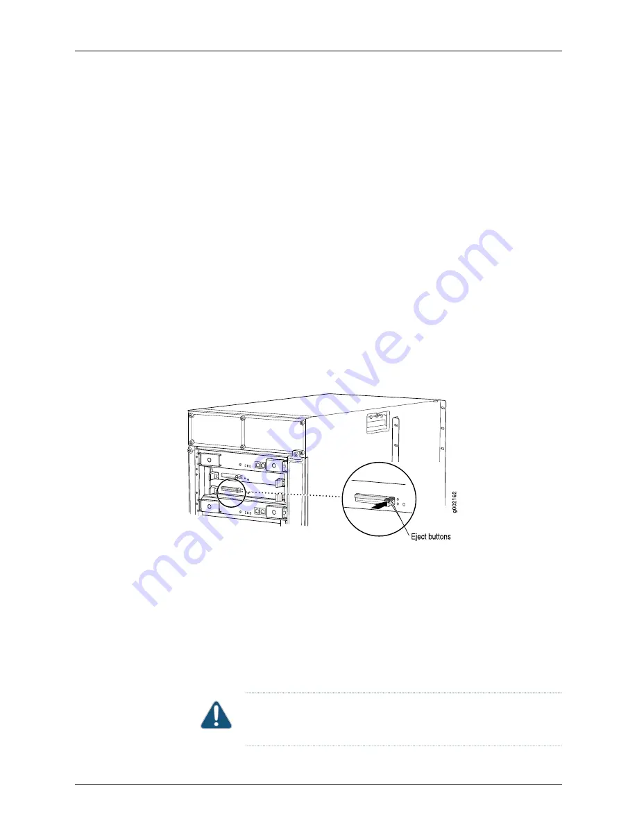
on the Routing Engine. To remove

the PC Card (see Figure 109 on page 252):

1.

Place an electrostatic bag or antistatic mat on a flat, stable surface.

2.

Attach an electrostatic discharge (ESD) grounding strap to your bare wrist, and connect
the strap to one of the ESD points on the chassis.

3.

If the Routing Engine cover is in place, remove the cover by loosening the captive
screws on the corners of its faceplate.

4.

On the Routing Engine faceplate, press the eject button on the right side of the PC
Card slot once to release the button. Press again to release the PC Card.

5.

The PC Card pops partially out of the slot. Grasp the card and pull it completely out
of the slot.

6.

Place the PC Card on the antistatic mat.

7.

If you are not replacing the PC Card now, reinstall the Routing Engine cover and tighten
the screws on the corners of the cover to secure it to the chassis.

Figure 109: Removing a PC Card

Installing a TX Matrix PC Card

To install a PC Card (see Figure 110 on page 253):

1.

Attach an electrostatic discharge (ESD) grounding strap to your bare wrist, and connect
the strap to one of the ESD points on the chassis.

2.

If the Routing Engine cover is in place, remove the cover by loosening the captive
screws on the corners of its faceplate.

3.

Insert the PC Card into the PC Card slot on the Routing Engine, with the Juniper
Networks logo facing downward.

CAUTION:

Be sure to insert the PC Card with the label facing downward.

Inserting the PC Card incorrectly might damage the Routing Engine.

Copyright © 2010, Juniper Networks, Inc.

252

TX Matrix Hardware Guide

Содержание TX MATRIX

Страница 1: ...TX Matrix Router Hardware Guide Published 2010 10 18 Copyright 2010 Juniper Networks Inc ...

Страница 2: ...mes no responsibility for any inaccuracies in this document Juniper Networks reserves the right to change modify transfer or otherwise revise this publication without notice Products made or sold by Juniper Networks or components thereof might be covered by one or more of the following patents that are owned by or licensed to Juniper Networks U S Patent Nos 5 473 599 5 905 725 5 909 440 6 192 051 ...

Страница 3: ...story YEAR 2000 NOTICE Juniper Networks hardware and software products are Year 2000 compliant The Junos OS has no known time related limitations through the year 2038 However the NTP application is known to have some difficulty in the year 2036 iii Copyright 2010 Juniper Networks Inc ...

Страница 4: ...are physically contained on a single chassis c Product purchase documents paper or electronic user documentation and or the particular licenses purchased by Customer may specify limits to Customer s use of the Software Such limits may restrict use to a maximum number of seats registered endpoints concurrent users sessions calls connections subscribers clusters nodes realms devices links ports or t...

Страница 5: ...RATE WITHOUT ERROR OR INTERRUPTION OR WILL BE FREE OF VULNERABILITY TO INTRUSION OR ATTACK In no event shall Juniper s or its suppliers or licensors liability to Customer whether in contract tort including negligence breach of warranty or otherwise exceed the price paid by Customer for the Software that gave rise to the claim or if the Software is embedded in another Juniper product the price paid...

Страница 6: ...ee years from the date of distribution Such request can be made in writing to Juniper Networks Inc 1194 N Mathilda Ave Sunnyvale CA 94089 ATTN General Counsel You may obtain a copy of the GPL at http www gnu org licenses gpl html and a copy of the LGPL at http www gnu org licenses lgpl html 15 Miscellaneous This Agreement shall be governed by the laws of the State of California without reference t...

Страница 7: ...Between the TX Matrix Router and T640 Router 10 TX Matrix Routing Matrix Switch Fabric Architecture 12 Switching Plane Connections Between the TX Matrix Router and T640 Routers 14 Chapter 3 TX Matrix Hardware Components Overview 17 TX Matrix Component Redundancy 18 TX Matrix Switch Card Chassis SCC Description 19 TX Matrix Midplane Description 21 TX Matrix Switch Interface Boards TX SIBs Overview ...

Страница 8: ...ix Two Input 160 A Power Supply Overview 41 Two Input 160 A DC Power Supply Description 41 Two Input 160 A DC Power Supply Inputs 42 Two Input 160 A DC Power Supply Load Sharing and Fault Tolerance 42 TX Matrix Two Input 160 A DC Power Supply LEDs 43 TX Matrix Three Input 240 A Power Supply Overview 44 Three Input 240 A DC Power Supply Description 44 Three Input 240 A DC Power Supply Inputs 45 Thr...

Страница 9: ...Router Mounting Hardware 75 Installing the TX Matrix Mounting Hardware for a Four Post Rack or Cabinet 75 Installing the Cage Nuts 76 Installing the Large Mounting Shelf 77 Installing the TX Matrix Spacer Bars on the Four Post Rack 77 Installing the Small Shelf 78 Installing the TX Matrix Mounting Hardware for an Open Frame Rack 79 Installing the Cage Nuts 79 Installing the Large Mounting Shelf 79...

Страница 10: ... Cable Shelf Assembly 108 Chapter 12 Grounding the TX Matrix Router 109 Connecting the Grounding Cable to the TX Matrix Router 109 Chapter 13 Routing the Fiber Optic Array Cables 111 Routing the TX Matrix Fiber Optic Array Cables 111 Chapter 14 Connecting the TX Matrix Router to External Devices 117 Tools and Parts Required for Connecting the TX Matrix Router to External Devices 117 Connecting to ...

Страница 11: ...the Configuration 144 TX Matrix Software and CLI Overview 145 TX Matrix Software 145 Running Different Junos OS Releases on the Routing Engines 145 Configuration Groups 146 PIC MAC Addresses 147 TX Matrix Interface Names Overview 147 SCC and LCC Interfaces 147 FPC Interfaces 148 Routing Engine Software Components 149 Routing Engine Software 149 Routing Protocol Process 149 IPv4 Routing Protocols 1...

Страница 12: ...hing Planes Between an Operational T640 Router and the TX Matrix Router 174 Converting a Switching Plane in a T640 Router 174 Connecting and Testing a Switching Plane Between a T640 Router and TX Matrix Router 175 Transferring Control from the T640 Router to the TX Matrix Router 177 Chapter 21 Integrating an Offline T640 Router with the TX Matrix Router 179 Overview of Integrating an Offline T640 ...

Страница 13: ...ace Alarm Messages 211 Troubleshooting the TX Matrix Cooling System 213 Troubleshooting the TX Matrix Power System 213 Troubleshooting the TX Matrix TX SIBs and the Switching Planes 216 Troubleshooting the TX SIB Adapters When an RX LED Is Not Steadily Green 218 Rolling Back the Integration of a T640 Router 219 Chapter 24 Replacing TX Matrix Hardware Components 223 TX Matrix Field Replaceable Unit...

Страница 14: ...lling a TX Matrix TX SIB 259 Replacing a TX Matrix Fiber Optic Array Cable 261 Removing a TX Matrix Fiber Optic Array Cable 262 Installing a TX Matrix Fiber Optic Array Cable 262 Verifying the Connections Between the TX Matrix TX SIBs and T640 SIBs 266 Replacing a TX Matrix Two Input 160 A DC Power Supply 269 Removing a TX Matrix Two Input 160 A DC Power Supply 269 Installing a TX Matrix Two Input...

Страница 15: ...ppression Equipment 303 TX Matrix General Installation Safety Guidelines 304 TX Matrix General Installation Safety Guidelines 304 TX Matrix Chassis Lifting Guidelines 304 Installation Safety Warnings for M Series MX Series and T Series Routers 304 Installation Instructions Warning 304 Rack Mounting Requirements and Warnings 305 Ramp Warning 308 TX Matrix Laser and LED Guidelines and Warnings 309 T...

Страница 16: ...ries MX Series and T Series Routers United States 330 Compliance Statements for Environmental Requirements for M Series MX Series and T Series Routers 330 TX Matrix Compliance Statements for Acoustic Noise 330 Appendix B TX Matrix Router Physical Specifications 333 TX Matrix Physical Specifications 333 Appendix C TX Matrix Router Environmental Specifications 335 TX Matrix Router Environmental Spec...

Страница 17: ...Need to Supply to JTAC 349 Returning a TX Matrix Router or Component 350 Displaying TX Matrix Component Serial Numbers 350 TX Matrix Component Serial Number Locations 351 TX Matrix Chassis Serial Number Label 351 TX CB Serial Number Label 352 TX CIP Serial Number Label 352 Craft Interface Serial Number Label 353 Power Supply Serial Number Label 353 Routing Engine Serial Number Label 354 TX SIB Ser...

Страница 18: ...Copyright 2010 Juniper Networks Inc xviii TX Matrix Hardware Guide ...

Страница 19: ...e 1600 RE 1600 29 Figure 14 Routing Engine 2000 RE 2000 31 Figure 15 TX CB 33 Figure 16 Front Panel of the Craft Interface 34 Figure 17 LCD display in Idle Mode 35 Figure 18 LCD Display in Alarm Mode 35 Figure 19 Alarm LEDs on the Craft Interface 36 Figure 20 TX Matrix Alarm Cutoff Lamp Test Button 37 Figure 21 TX CIP 39 Figure 22 Two Input 160 A DC Power Supply 42 Figure 23 Three Input 240 A DC P...

Страница 20: ...ter 93 Figure 48 Removing a TX CB 94 Figure 49 Removing the Rear Fan Tray 95 Figure 50 Removing a TX SIB 96 Figure 51 Removing a Front Fan Tray 97 Figure 52 Attaching the Installation Handle 98 Figure 53 Installing the TX Matrix Chassis in the Rack 100 Figure 54 Reinstalling the Rear Fan Tray 101 Figure 55 Reinstalling a TX CB 102 Figure 56 Reinstalling a Power Supply 103 Figure 57 Reinstalling a ...

Страница 21: ...Router 169 Figure 80 Cleaning Tool and Adapter 171 Chapter 21 Integrating an Offline T640 Router with the TX Matrix Router 179 Figure 81 T CB 181 Figure 82 Switching Planes Connections 185 Part 4 Hardware Maintenance Troubleshooting and Replacement Procedures Chapter 22 Maintaining TX Matrix Router Hardware Components 193 Figure 83 Cleaning Tool and Adapter 201 Figure 84 Inserting the Fiber Optic ...

Страница 22: ...er Supply 270 Figure 120 Removing a Two Input 160 A Power Supply 271 Figure 121 Rear of the Power Supply Showing Midplane Connectors 272 Figure 122 Installing a Replacement Two Input 160 A DC Power Supply 274 Figure 123 Connecting Power Cables to a Two Input 160 A DC Power Supply 275 Figure 124 Disconnecting Power Cables from the DC Power Supply 276 Figure 125 Rear of the Power Supply Showing Midp...

Страница 23: ...the TX Matrix Router 337 Figure 144 Grounding Cable Lug 338 Figure 145 Power Cable Lug 342 Figure 146 Typical DC Source Cabling from PEM0 to Feed A 343 Figure 147 Typical DC Source Cabling from PEM1 to Feed B 343 Appendix F Contacting Customer Support and Returning TX Matrix Hardware 349 Figure 148 Serial Number ID Label 351 Figure 149 TX Matrix Chassis Serial Number Label 352 Figure 150 TX CB Ser...

Страница 24: ...Copyright 2010 Juniper Networks Inc xxiv TX Matrix Hardware Guide ...

Страница 25: ...Table 12 TX Matrix Components Powered by Each Input 42 Table 13 Fault Tolerance 43 Table 14 Two Input 160 A DC Power Supply LEDs 43 Table 15 Components Powered by Each Three Input 240 A DC Power Supply Input 45 Table 16 Fault Tolerance 46 Table 17 Three Input 240 A DC Power Supply LEDs 46 Part 2 Setting Up the TX Matrix Router Chapter 6 Unpacking the TX Matrix Router 69 Table 18 TX Matrix Router P...

Страница 26: ...ix Router Physical Specifications 333 Table 31 Physical Specifications 333 Appendix C TX Matrix Router Environmental Specifications 335 Table 32 TX Matrix Router Environmental Specifications 335 Appendix D Power Guidelines Requirements and Specifications for the TX Matrix Router 337 Table 33 Grounding Cable Specifications 338 Table 34 Power System Electrical Specifications 338 Table 35 T640 Two In...

Страница 27: ...ww juniper net techpubs Objectives This documentation describes hardware components installation basic configuration and basic troubleshooting procedures for the Juniper Networks TX Matrix Internet Router s It explains how to prepare your site for router installation unpack and install the hardware power on the router perform initial software configuration and perform routine maintenance After com...

Страница 28: ...damage Caution Alerts you to the risk of personal injury or death Warning Alerts you to the risk of personal injury from a laser Laser warning Table 2 on page xxviii defines the text and syntax conventions used in this guide Table 2 Text and Syntax Conventions Examples Description Convention To enter configuration mode type the configure command user host configure Represents text that you type Bo...

Страница 29: ...p Required for dynamic MPLS only Indicates a comment specified on the same line as the configuration statement to which it applies pound sign community name members community ids Enclose a variable for which you can substitute one or more values square brackets edit routing options static route default nexthop address retain Identify a level in the configuration hierarchy Indention and braces Iden...

Страница 30: ... a day 7 days a week 365 days a year Self Help Online Tools and Resources For quick and easy problem resolution Juniper Networks has designed an online self service portal called the Customer Support Center CSC that provides you with the following features Find CSC offerings http www juniper net customers support Search for known bugs http www2 juniper net kb Find product documentation http www ju...

Страница 31: ...in the CSC at http www juniper net cm Call 1 888 314 JTAC 1 888 314 5822 toll free in the USA Canada and Mexico For international or direct dial options in countries without toll free numbers see http www juniper net support requesting support html xxxi Copyright 2010 Juniper Networks Inc About the Documentation ...

Страница 32: ...Copyright 2010 Juniper Networks Inc xxxii TX Matrix Hardware Guide ...

Страница 33: ...1 Overview of the TX Matrix Router TX Matrix Router Overview on page 3 TX Matrix System Architecture Overview on page 5 TX Matrix Hardware Components Overview on page 17 1 Copyright 2010 Juniper Networks Inc ...

Страница 34: ...Copyright 2010 Juniper Networks Inc 2 TX Matrix Hardware Guide ...

Страница 35: ...single physical topology This gives you the ability to virtually separate traffic types that require unique network attributes such as ATM or high priority voice over IP VoIP and third generation 3G mobile traffic from bulk transit IP traffic The TX Matrix router architecture cleanly separates control operations from packet forwarding operations This design eliminates processing and traffic bottle...

Страница 36: ...Copyright 2010 Juniper Networks Inc 4 TX Matrix Hardware Guide ...

Страница 37: ...control plane and the forwarding plane The control plane in the routing matrix is formed by the connection of the host subsystems TX CBs in the TX Matrix router and T CBs in the T640 routers and the Routing Engines The forwarding plane in the routing matrix is formed by the switch fabric TX SIBs in the TX Matrix router and T640 SIBs in the T640 routers and the Packet Forwarding Engines The Routing...

Страница 38: ...software processes that control chassis components and system management For more information about the processes see Routing Engine Software Components on page 149 The Routing Engines include the following functions and features Processing of routing protocol packets The Routing Engine handles all packets that concern routing protocols freeing the Packet Forwarding Engine to handle only packets t...

Страница 39: ...e management Configuration files system images and microcode can be held and maintained in primary and secondary storage systems permitting local or remote upgrades Monitoring efficiency and flexibility The TX Matrix router supports functions such as alarm handling and packet counting on every port without degrading packet forwarding performance The TX Matrix Routing Engine constructs and maintain...

Страница 40: ... All master Routing Engines in the TX Matrix router and T640 routers are on one control plane all backup Routing Engines are on another control plane see Figure 3 on page 9 To manage the Routing Engines on a control plane you must be logged into the Routing Engine in the TX Matrix router on that control plane For example you must be logged into the backup Routing Engine in the TX Matrix router to ...

Страница 41: ... the TX CIPs and the T CBs in the T640 routers The kernel synchronization process running on each T640 router Routing Engine synchronizes the TX Matrix Routing Engine s forwarding table with the forwarding table on a T640 router The Junos kernel running on each T640 router Routing Engine copies its forwarding table to all Packet Forwarding Engines in each T640 router Figure 4 on page 10 illustrate...

Страница 42: ...trix router and the T CBs in the T640 routers The maximum length supported is 100 m The UTP Category 5 cables do not have to be the same length The cable wiring is straight through not crossover Table 3 on page 11 shows these connections Each column represents a TX CIP TX CIP 0 and TX CIP 1 and each cell within a column represents a port on that TX CIP Each cell specifies the TX CIP port LCC0 thro...

Страница 43: ... are presented in the first two rows of the table and so on NOTE The RJ 45 ports labeled LCC4 through LCC7 on a TX CIP are reserved for future use Table 3 Cable Connections between TX CIPs and T CBs TX CIP 1 Port and Destination TX CIP 0 Port and Destination LCC0 T CB 1 in LCC0 LCC0 T CB 0 in LCC0 LCC1 T CB 1 in LCC1 LCC1 T CB 0 in LCC1 LCC2 T CB 1 in LCC2 LCC2 T CB 0 in LCC2 LCC3 T CB 1 in LCC3 L...

Страница 44: ... a data switching plane that spans the TX Matrix router and all T640 routers in the routing matrix The switching planes are connected by high speed optical links within fiber optic array cables Consider a packet that enters a T640 router and is destined for another T640 router in the routing matrix When the packet enters an interface on a PIC in a T640 router it is forwarded to the switch fabric b...

Страница 45: ...face The switch fabric can forward up to 3 Gpps The maximum aggregate throughput rate for the TX Matrix router is 2 56 Tbps full duplex Figure 6 on page 13 illustrates the switch fabric architecture Figure 6 Routing Matrix Switch Fabric Architecture Related Documentation TX Matrix Router Description on page 3 TX Matrix System Architecture Description on page 5 Switching Plane Connections Between t...

Страница 46: ...ctions from each TX SIB to chassis LCC0 and LCC1 are presented in the first two rows of the table and so on Table 4 Fiber Optic Array Cable Connections Between TX SIBs and T640 SIBs TX SIB 4 Adapter and Destination TX SIB 3 Adapter and Destination TX SIB 2 Adapter and Destination TX SIB 1 Adapter and Destination TX SIB 0 Adapter and Destination LCC0 T640 SIB 4 in LCC0 LCC0 T640 SIB 3 in LCC0 LCC0 ...

Страница 47: ...mentation TX Matrix Router Description on page 3 TX Matrix System Architecture Description on page 5 TX Matrix Routing Matrix Switch Fabric Architecture on page 12 15 Copyright 2010 Juniper Networks Inc Chapter 2 TX Matrix System Architecture Overview ...

Страница 48: ...Copyright 2010 Juniper Networks Inc 16 TX Matrix Hardware Guide ...

Страница 49: ...on on page 25 TX Matrix Routing Engine Overview on page 25 TX Matrix Control Board TX CB Overview on page 32 TX Matrix Craft Interface Overview on page 34 TX Matrix Craft Interface LED Overview on page 36 TX Matrix Connector Interface Panel TX CIP Overview on page 38 TX Matrix Power System Overview on page 41 TX Matrix Cooling System Overview on page 47 TX Matrix Cables Overview on page 49 TX Matr...

Страница 50: ... Routing Engine automatically synchronizes its configuration and state with the master Routing Engine Any update to the master Routing Engine state is replicated on the backup Routing Engine If the backup Routing Engine assumes mastership packet forwarding continues through the TX Matrix router without interruption For more information about graceful switchover see the Junos OS High Availability C...

Страница 51: ... lb 225 kg The chassis includes the following features see Figure 8 on page 20 and Figure 9 on page 21 A pair of metal flanges and a pair of metal brackets used for mounting the chassis in a four post rack or cabinet or open frame rack Upper and lower handles on each side to facilitate positioning the TX Matrix router in the rack Do not use the handles to lift the TX Matrix router Two electrostati...

Страница 52: ...Figure 8 Front View of the TX Matrix Router Copyright 2010 Juniper Networks Inc 20 TX Matrix Hardware Guide ...

Страница 53: ...337 TX Matrix Midplane Description The midplane is located in the center of the chassis and forms the rear of the TX SIB card cage see Figure 10 on page 22 The TX SIBs install into the midplane from the front of the chassis and the Routing Engines and TX CBs install into the midplane from the rear of the chassis The power supplies and cooling system components also connect to the midplane 21 Copyr...

Страница 54: ...onnectivity between all TX Matrix components for monitoring and controlling the system Redundancy connectivity The midplane provides redundant paths for all critical connections Figure 10 TX Matrix Router Midplane Related Documentation TX Matrix Router Description on page 3 TX Matrix Component Redundancy on page 18 TX Matrix Switch Card Chassis SCC Description on page 19 Copyright 2010 Juniper Net...

Страница 55: ... When the failed component is replaced the data switching plane in which it resides becomes the new backup If the failed component is not replaced and a TX SIB or T640 SIB in an active data switching plane fails only that component is taken offline TX SIBs are hot removable and hot insertable Each TX SIB consists of the following components Switch fabric ASICs A high speed fiber optic link to each...

Страница 56: ...te the status of the TX SIB see Table 5 on page 24 Each TX SIB has three additional LEDs on the craft interface that show its status Table 5 TX SIB LEDs Description State Color Label Receive link is offline Off RX Receive link is powering on Blinking Green Receive link is online and functioning normally On steadily Green Fiber optic array cable might be connected to the wrong T640 SIB On steadily ...

Страница 57: ... each host subsystem functions as a unit the Routing Engine requires the corresponding TX CB and vice versa NOTE We recommend that you install two host subsystems for redundant protection If you install only one host subsystem we recommend that you install it in slot RE0 Related Documentation TX Matrix Control Board TX CB Description on page 32 TX Matrix Routing Engine Description on page 26 TX Ma...

Страница 58: ...nge in Routing Engine mastership can cause one or all T640 routers to be logically disconnected from the TX Matrix router Each Routing Engine requires a TX CB to be installed in the adjacent slot RE0 installs below CB0 and RE1 installs above CB1 A Routing Engine does not power on if no TX CB is present in the adjacent slot The ports for connecting the Routing Engine to external management devices ...

Страница 59: ...management access Provide information about Routing Engine status to devices console laptop or terminal server connected to ports located on the Connector Interface Panel CIP The faceplate of the Routing Engine 600 contains the following One PC Card slot Accepts a removable PC Card which stores software images for system upgrades A slot labeled PC CARD on the Routing Engine faceplate accepts a Typ...

Страница 60: ...age 28 TX Matrix RE 600 LEDs The HD LED indicates activity on the hard drive It does not necessarily indicate routing related activity NOTE The LEDs that report host module status including Routing Engine status are on the craft interface rather than the Routing Engine faceplate Related Documentation TX Matrix Host Subsystem Description on page 25 TX Matrix RE 600 Description on page 27 TX Matrix ...

Страница 61: ... 1600 contains the following Two PC Card slots Accept removable PC Cards which store software images for system upgrades Each PC card slot accepts a Type I PC Card as defined in the PC Card Standard published by the Personal Computer Memory Card International Association PCMCIA The TX Matrix router is shipped with a PC Card that contains Junos OS The PC Card can be used to copy Junos OS from the P...

Страница 62: ...the functions of these LEDs Table 6 RE 1600 LEDs Description State Color Label Indicates activity on the hard drive On steadily or blinking Yellow HD Indicates that the Routing Engine is booting and the firmware is checking if a PC card is installed Blinking Red and Green alternately Slot LEDs 0 and 1 Indicates that the Routing Engine booted from the PC Card On steadily Green Related Documentation...

Страница 63: ...ation about Routing Engine status to devices console laptop or terminal server connected to the Routing Engine ports located on the CIP The faceplate of the RE 2000 contains the following USB port Provides a removable media interface through which you can install the Junos OS manually The Junos OS supports USB version 1 0 Reset button Reboots the Routing Engine when pressed Offline button Takes th...

Страница 64: ...d TX CB LEDs on page 34 TX Matrix Control Board TX CB Description Each TX CB works with an adjacent Routing Engine to provide control and monitoring functions for the TX Matrix router see Figure 15 on page 33 These functions include determining Routing Engine mastership controlling power and reset for the other TX Matrix router components monitoring and controlling fan speed and monitoring system ...

Страница 65: ...e the status of the TX CB Table 8 on page 34 describes the functions of the TX CB LEDs Online offline button located on the TX CB faceplate This button is nonfunctional Two configuration switches located on the TX CB faceplate NOTE The M S and CHASSIS ID switches on the TX CB faceplate must always be set to S and 0 Two RJ 45 ports labeled AUX and CIP on the TX CB faceplate These ports are not used...

Страница 66: ... TX CB Description on page 32 TX Matrix Craft Interface Overview TX Matrix Craft Interface Overview on page 34 TX Matrix Craft Interface Overview Craft Interface Front Panel on page 34 TX SIB Online Offline Buttons on page 35 LCD display and Navigation Buttons on page 35 Craft Interface Front Panel The craft interface allows you to view status and troubleshooting information at a glance and to per...

Страница 67: ...nes in the display report the following information First line TX Matrix router name Second line Length of time the TX Matrix router has been running reported in the following form Up days hours minutes Third and fourth lines Status messages which rotate at 2 second intervals Some conditions such as removal or insertion of a system component can interrupt the messages To add a message that alterna...

Страница 68: ...face on page 37 TX Matrix Host Subsystem LEDs on the Craft Interface on page 37 TX Matrix TX SIB LEDs on the Craft Interface on page 38 TX Matrix Alarm LEDs on the Craft Interface Two large alarm LEDs are located at the left of the craft interface see Figure 19 on page 36 Both LEDs can be lit simultaneously The circular red LED lights to indicate a critical condition that can result in a system sh...

Страница 69: ...ce attached to the corresponding alarm relay contact on the TX CIP However the LCD display continues to report the alarm message until you clear the condition that caused the alarm Figure 20 TX Matrix Alarm Cutoff Lamp Test Button To deactivate red and yellow alarms press the button labeled ACO LT for alarm cutoff lamp test Related Documentation TX Matrix Craft Interface Overview on page 34 TX Mat...

Страница 70: ...he TX SIB online offline buttons SIB0 through SIB4 Table 11 on page 38 describes the functions of the TX SIB LEDs Table 11 TX SIB LEDs on the Craft Interface Description State Color Label TX SIB is passing traffic On steadily Green ACTIVE TX SIB is not passing traffic Off TX SIB is functioning normally On steadily Green OK TX SIB is coming online Blinking TX SIB has failed On steadily Red FAIL Rel...

Страница 71: ...assis in the slots labeled CIP0 and CIP1 see Figure 21 on page 39 The TX CIPs are referred to as TX CIP 0 and TX CIP 1 The front electrostatic discharge point is located near the bottom of the TX CIP The TX CIP is hot removable and hot insertable Figure 21 TX CIP 39 Copyright 2010 Juniper Networks Inc Chapter 3 TX Matrix Hardware Components Overview ...

Страница 72: ... left edge of the port indicate the connection in use the LED labeled ETHERNET lights yellow or green for a 10 Mbps or 100 Mbps connection and the LED labeled ACT lights green when traffic is passing through the port NOTE If a TX Matrix router contains two host subsystems connect both TX CIPs to your external management network CONSOLE One asynchronous serial port for connecting the Routing Engine...

Страница 73: ...ply is cooled by its own internal cooling system The TX Matrix router supports these DC power supplies The two input 160 A DC power supply is supported by Junos OS Release 5 3 and later The three input 240 A DC power supply in 2 INPUT mode is supported by Junos OS Release 9 2 and later NOTE Mixingatwo input160 Apowersupplyandathree input240 Apower supply in the same chassis is not supported during...

Страница 74: ...ents are powered by each input Table 12 TX Matrix Components Powered by Each Input Provides Power to These Components Input SIBs in slot 2 3 and 4 INPUT 0 SIB in slots 0 and 1 control boards Routing Engines CIP craft interface and fan trays INPUT 1 Two Input 160 A DC Power Supply Load Sharing and Fault Tolerance When the router is operating normally and both power supplies in a redundant power sys...

Страница 75: ...on page 338 TX Matrix Two Input 160 A DC Power Supply LEDs Four LEDs on each two input 160 A DC power supply faceplate indicate the status of the power supply In addition a power supply failure triggers the red alarm LED on the craft interface Table 14 on page 43 describes the functions of the power supply LEDs Table 14 Two Input 160 A DC Power Supply LEDs Description State Color LED Circuit break...

Страница 76: ...wer Supplies on page 203 Troubleshooting the TX Matrix Power System on page 213 TX Matrix DC Power Supply Specifications on page 338 TX Matrix Three Input 240 A Power Supply Overview Three Input 240 A DC Power Supply Description on page 44 Three Input 240 A DC Power Supply Inputs on page 45 Three Input 240 A DC Power Supply Load Sharing and Fault Tolerance on page 45 Three Input 240 A DC Power Sup...

Страница 77: ... Input Three Input Mode Input T640 SIBs T CBs fan trays Routing Engines and FPCs in slots FPC0 and FPC1 INPUT 0 FPCs in slots FPC2 through FPC7 INPUT 1 This input is not supported in 2 INPUT mode INPUT 2 Three Input 240 A DC Power Supply Load Sharing and Fault Tolerance When the router is operating normally and both power supplies are switched on load sharing between them occurs automatically When...

Страница 78: ... page 203 Troubleshooting the TX Matrix Power System on page 213 TX Matrix DC Power Supply Specifications on page 338 TX Matrix Three Input 240 A Power Supply LEDs LEDs on each power supply faceplate see Figure 24 on page 46 indicate the status of the power supply In addition a power supply failure triggers the red alarm LED on the craft interface Table 17 on page 46 describes the functions of the...

Страница 79: ...mmended temperature On steadily Yellow OVER TEMP One per power supply Power supply is within the recommended temperature or the power supply is not on Off Related Documentation TX Matrix Cooling System Overview Cooling System Description on page 47 Fan Tray Description on page 48 Air Filter Description on page 49 Cooling System Description The cooling system components work together to keep all TX...

Страница 80: ... page 21 The fan trays each contain multiple fans that work in unison to cool the TX Matrix router components The fan trays are hot insertable and hot removable Figure 25 on page 48 shows the airflow through the TX Matrix router The front fan trays each contain six fans and are interchangeable with each other The front fan trays cool the components installed in the front card cage the TX SIBs TX C...

Страница 81: ...with the rear fan tray removed for more than 1 minute Air Filter Description Air filters for both the front and rear fan trays help keep dust and other particles from entering the cooling system The TX Matrix router has one front air filter and one rear air filter The air filter is hot insertable and hot removable Related Documentation TX Matrix Cables Overview Fiber optic Array Cables on page 49 ...

Страница 82: ...g matrix Controlling the T640 routers requires connections from the two TX CIPs in the TX Matrix router to the T CBs in the T640 routers Out of band management requires connections from the TX CIPs to external management devices These cables can be up to 100 m long DB 9 Serial Cables The DB 9 serial cables are used to connect a system console or laptop computer to the TX CIPs for local management ...

Страница 83: ...n relief to the four fiber optic array cables connected to the TX SIB immediately below it The fiber optic array cables extend through the top of the cable comb so that you can route the cables to the T640 routers The cable shelf assembly routes and supports the fiber optic array cables over the top of the TX Matrix router see Figure 28 on page 52 The cable shelf assembly consists of four parallel...

Страница 84: ... cable bend radius Figure 28 Cable Shelf Assembly Related Documentation TX Matrix Cables Overview on page 49 TX Matrix Fiber Optic Array Cable Considerations on page 65 Routing the TX Matrix Fiber Optic Array Cables on page 111 Copyright 2010 Juniper Networks Inc 52 TX Matrix Hardware Guide ...

Страница 85: ...hassis Using a Mechanical Lift on page 85 Installing the TX Matrix Chassis Without a Mechanical Lift on page 91 Installing the TX Matrix Cable Management System on page 107 Grounding the TX Matrix Router on page 109 Routing the Fiber Optic Array Cables on page 111 Connecting the TX Matrix Router to External Devices on page 117 Providing Power to the TX Matrix Router on page 125 Testing and Connect...

Страница 86: ...Copyright 2010 Juniper Networks Inc 54 TX Matrix Hardware Guide ...

Страница 87: ...or Installing the TX Matrix Mounting Hardware for an Open Frame Rack on page 79 5 Install the TX Matrix chassis See Overview of Installing the TX Matrix Chassis on page 83 Because of the TX Matrix router s size and weight up to 495 lb 225 kg depending on configuration we strongly recommend that you install the TX Matrix chassis using a lift 6 Install the TX Matrix cable management system See Insta...

Страница 88: ...e initial system startup See PerformingtheInitialSoftwareConfigurationfortheTXMatrixRouter onpage142 13 Convert and integrate the T640 routers into the routing matrix See Overview of Converting and Integrating a T640 Router on page 159 14 Verify the state of the TX Matrix and T640 routers See Verifying the State of the Routing Matrix on page 186 15 For each T640 router configure specific LCC chass...

Страница 89: ...d TX Matrix router tolerances See TX Matrix Router Environmental Specifications on page 335 2 Choose the routing matrix configuration centralized or distributed See TX Matrix Routing Matrix Hardware Configurations on page 58 3 Measure the distance between external power sources and the TX Matrix router installation site TX Matrix DC Power Cable and Lug Specifications on page 341 4 Locate sites for...

Страница 90: ...cks 20 fiber optic array cables 10 Ethernet cables and a cable management system There are two types of configurations to consider when you plan and prepare for the installation of the routing matrix centralized and distributed Centralized Configuration In the centralized configuration three racks are placed next to each other in a row Figure 29 on page 59 and Figure 30 on page 59 show a rack view...

Страница 91: ...nt allows you to connect the T640 routers to the TX Matrix router using the fiber optic array cables The maximum cable length is 100 m The total weight and heat dissipation of the routing matrix are important in the distributed configuration but not as critical as in the centralized configuration For physical and environmental specifications see Table 31 on page 333 and TX Matrix Router Environmen...

Страница 92: ... cables contact your customer support representative before you connect the T640 router and TX Matrix router Figure 31 Distributed Configuration Related Documentation TX Matrix Fiber Optic Array Cable Considerations on page 65 TX Matrix Physical Specifications on page 333 TX Matrix Router Environmental Specifications on page 335 Copyright 2010 Juniper Networks Inc 60 TX Matrix Hardware Guide ...

Страница 93: ...T640 router in the bottom of an empty rack reserve the top of the rack for the future installation of another T640 router We recommend that you install the TX Matrix router in its own dedicated rack If you must install another device in the rack consider the height and weight of the TX Matrix router and the fiber optic array cable management above the chassis including the optional cable shelf ass...

Страница 94: ...ter of the chassis for rack mounting if front mounting is used you use the front mounting flanges Before you mount the TX Matrix router in a four post rack or cabinet you must install the spacer bars on the rack For instructions aboutinstalling the mounting hardware see Installing the TX Matrix Mounting Hardware for a Four Post Rack or Cabinet on page 75 The chassis height of 44 5 in 113 0 cm is a...

Страница 95: ...g If your geographical area is subject to earthquakes bolt the rack to the floor For maximum stability also secure the rack to ceiling brackets For more information see Rack Mounting Requirements and Warnings on page 305 Related Documentation TX Matrix Routing Matrix Hardware Configurations on page 58 Installation Safety Warnings for M Series MX Series and T Series Routers on page 304 TX Matrix Cl...

Страница 96: ...components there must be adequate space at the front and back of the rack Allow at least 30 in 72 6 cm in front of the rack and 24 in 61 0 cm behind the rack see Figure 34 on page 64 Figure 34 Chassis Dimensions and Clearance Requirements Related Documentation TX Matrix Cooling System Overview on page 47 Maintaining the TX Matrix Air Filters on page 194 Maintaining the TX Matrix Fan Trays on page ...

Страница 97: ...m a particular T640 router to the TX Matrix router However you do not need to use the same length for all fiber optic array cables within a routing matrix For example if your routing matrix contains two T640 routers you can use 6 meter fiber optic array cables to one router and 100 meter fiber optic array cables to the other router You must maintain a minimum bend radius of 2 in 5 1 cm We recommen...

Страница 98: ...36 T640 SIB Plan the management of the fiber optic array cables between the T640 routers and the TX Matrix router keeping in mind the following considerations With four T640 routers you can have a total of 20 fiber optic array cables in a routing matrix NOTE We recommend that you purchase one additional fiber optic array cable for each T640 router in the TX Matrix router in case one of the cables ...

Страница 99: ... T640 Core Router PIC Guide Figure 37 Fiber Optic Array Cable Related Documentation TX Matrix Cables Overview on page 49 Switching Plane Connections Between the TX Matrix Router and T640 Routers on page 14 67 Copyright 2010 Juniper Networks Inc Chapter 5 Preparing the Site for TX Matrix Router Installation ...

Страница 100: ...Copyright 2010 Juniper Networks Inc 68 TX Matrix Hardware Guide ...

Страница 101: ... the shipping crate See Unpacking the TX Matrix Router on page 70 3 Verify that all parts have been received See Verifying the TX Matrix Parts Received on page 71 Tools and Parts Required for Unpacking the TX Matrix Router To unpack the TX Matrix router and prepare for installation you need the following tools Phillips screwdriver number 2 1 2 in or 13 mm open end or socket wrench to remove bracke...

Страница 102: ...bolted to the pallet you can use a forklift or pallet jack to move it 2 Position the shipping crate with the arrows pointing up 3 Open all the latches on the shipping crate 4 Remove the front door of the shipping crate cover and set it aside 5 Slide the remainder of the shipping crate cover off the pallet 6 Remove the foam covering the top of the TX Matrix router 7 Remove the accessory box and the...

Страница 103: ...The packing list specifies the part numbers and descriptions of each part in your order To verify that the TX Matrix parts have been received 1 Verify that all the parts in the main shipment Table 18 on page 71 which contains the TX Matrix chassis with installed components have been received 2 Verify that all the parts in the accessory box Table 19 on page 72 have been received 3 If any part is mi...

Страница 104: ...out components installed Table 19 Accessory Box Parts List Quantity Part 1 2 5 mm ball hex driver for the fiber optic array loopback adapter and loopback connector 1 7 16 in 11 mm nut driver or socket wrench 1 Affidavit for T1 connection 2 Connectors for alarm relay cables 1 DB 9 male to DB 25 female adapter 9 8 for power 1 for grounding DC power and grounding cable lugs 1 ESD wrist strap with cab...

Страница 105: ...unding cable to chassis Bag of 14 Screws to mount chassis 1 Serial cable 6 ft length to connect Routing Engine to management console 1 Software license agreement 1 Ethernet cable 15 ft length to connect Routing Engine to management device 2 Washers for grounding cable lug Related Documentation Overview of Unpacking the TX Matrix Router on page 69 Tools and Parts Required for Unpacking the TX Matri...

Страница 106: ...Copyright 2010 Juniper Networks Inc 74 TX Matrix Hardware Guide ...

Страница 107: ...trix Mounting Hardware for an Open Frame Rack on page 79 Removing the Center Mounting Brackets on page 80 Installing the TX Matrix Mounting Hardware for a Four Post Rack or Cabinet Before installing the TX Matrix router into a four post rack or cabinet install the large and small mounting shelves and the spacer bars on the rack 75 Copyright 2010 Juniper Networks Inc ...

Страница 108: ...s specified in Table 20 on page 77 for the large mounting shelf and the spacer bars 2 On the rear rack rails install cage nuts in the holes specified in Table 20 on page 77 for the small mounting shelf Table 20 on page 77 specifies the holes in which you insert cage nuts and screws to install the mounting hardware required in a four post or cabinet rack an X indicates a mounting hole location The ...

Страница 109: ... mounting shelf on the front rack rails Rest the bottom slot of each flange on a mounting screw 3 Tighten all the screws completely Installing the TX Matrix Spacer Bars on the Four Post Rack The TX Matrix router is shipped with each spacer bar attached to the rear of a front mounting flange If you are mounting the TX Matrix router in a four post rack or cabinet you must install the spacer bars on ...

Страница 110: ...age nut 2 Install the small mounting shelf on the back rack rails Rest the bottom slot of each flange on a mounting screw The small mounting shelf installs on the back of the rear rails extending toward the center of the rack The bottom of the small mounting shelf should align with the bottom of the large mounting shelf 3 Partially insert screws into the open holes in the flanges of the small moun...

Страница 111: ... is at 0 04 in 0 02 U above a U division Table 21 Open Frame Rack Mounting Hole Locations Front Shelf Distance Above U Division Hole X 19 50 U 34 13 in 86 7 cm 59 X 17 50 U 30 63 in 77 8 cm 53 X 16 50 U 28 88 in 73 3 cm 50 X 14 50 U 25 38 in 64 5 cm 44 X 13 50 U 23 63 in 60 0 cm 41 X 11 50 U 20 13 in 51 1 cm 35 X 10 50 U 18 38 in 46 7 cm 32 X 10 14 U 17 75 in 45 1 cm 31 Installing the Large Mounti...

Страница 112: ...rews that fasten it to the front mounting flange Related Documentation Rack Requirements for TX Matrix Routers on page 61 Removing the Center Mounting Brackets on page 80 Removing the Center Mounting Brackets If you are installing the router in a four post rack or front mounting the router in an open frame rack you must also remove the mounting brackets from the chassis Copyright 2010 Juniper Netw...

Страница 113: ...g the Center Mounting Brackets Related Documentation TX Matrix Switch Card Chassis SCC Description on page 19 Installing the TX Matrix Mounting Hardware for a Four Post Rack or Cabinet on page 75 Installing the TX Matrix Mounting Hardware for an Open Frame Rack on page 79 81 Copyright 2010 Juniper Networks Inc Chapter 7 Installing the TX Matrix Router Mounting Hardware ...

Страница 114: ...Copyright 2010 Juniper Networks Inc 82 TX Matrix Hardware Guide ...

Страница 115: ... the Site for the TX Matrix Router on page 57 3 3 Because of the router s size and weight up to 495 lb 225 kg fully configured we strongly recommend that you lift the chassis into the rack using a mechanical lift See Overview of Installing the TX Matrix Chassis Using a Mechanical Lift on page 85 However if a mechanical lift is not available you can remove components from the chassis to make it eas...

Страница 116: ...Copyright 2010 Juniper Networks Inc 84 TX Matrix Hardware Guide ...

Страница 117: ...o install the TX Matrix Router Tools Required to Install the TX Matrix Chassis Using a Mechanical Lift on page 85 2 Install the TX Matrix chassis into the rack using a mechancal lift Installing the TX Matrix Chassis Using a Mechanical Lift on page 85 Tools Required to Install the TX Matrix Chassis Using a Mechanical Lift To install the TX Matrix chassis you need the following tools Mechanical lift...

Страница 118: ...ctions for your site 2 Switch both circuit breakers on the power supply faceplate to the off position O We recommend this even though the power supplies are not connected to power sources 3 Loosen the captive screws on the lower corners of the power supply faceplate completely 4 Twist the ejector handles on the upper corners of the faceplate counterclockwise to unseat the power supply 5 Grasp the ...

Страница 119: ...atic discharge ESD grounding strap to your bare wrist and connect the strap to an approved site ESD grounding point See the instructions for your site 2 Insert the captive screws of the handle into the holes previously occupied by the captive screws of the power supplies see Figure 44 on page 87 3 Tighten the screws using a Phillips screwdriver number 2 Figure 44 Attaching the Installation Handle ...

Страница 120: ...e chassis and the mounting shelves overlap by approximately 2 inches 6 With one person pulling on the installation handle from the rear of the rack or cabinet while two people push on the front mounting flanges slide the TX Matrix chassis onto the mounting shelves until the mounting brackets or front mounting flanges contact the rack rails or spacer bars depending on your type of installation The ...

Страница 121: ...nstallation handle 1 Attach an electrostatic discharge ESD grounding strap to your bare wrist and connect the strap to an approved site ESD grounding point See the instructions for your site 2 Using a Phillips screwdriver number 2 loosen the captive screws on the installation handle completely 3 Remove the handle from the chassis 89 Copyright 2010 Juniper Networks Inc Chapter 9 Installing the TX M...

Страница 122: ...into the chassis until you feel resistance 4 Twist the ejector handles at the upper corners of the power supply faceplate clockwise until they stop 5 Tighten the captive screws at the lower corners of the power supply faceplate to secure the power supply in the chassis 6 Repeat the procedure for the other power supply Figure 46 Reinstalling a Power Supply Related Documentation Overview of Installi...

Страница 123: ...s Without a Mechanical Lift Before installing the TX Matrix chassis make sure that you have prepared your site unpacked the router from the shipping crate and installed the mounting hardware To install the TX Matrix router 1 Gather the tools required to install the TX Matrix chassis Tools and Parts Required to Install the TX Matrix Chassis Without a Mechanical Lift on page 92 2 Remove the TX Matri...

Страница 124: ...rom the front 1 Removing the Power Supplies on page 92 2 Removing the TX CBs on page 93 3 Removing the Rear Fan Tray on page 94 4 Removing the TX SIBs on page 95 5 Removing the Front Fan Trays on page 97 Removing the Power Supplies The power supplies are located at the lower rear of the chassis Each two input 160 A power supply weighs approximately 23 lb 10 5 kg Each three input 240 A power supply...

Страница 125: ... The TX Matrix router can have up to two TX CBs These are located in the upper rear of the chassis in the slots marked CB0 and CB1 Each one weighs approximately 5 lb 2 3 kg To remove the TX CBs see Figure 48 on page 94 1 Place an electrostatic bag or antistatic mat on a flat stable surface 2 Attach an electrostatic discharge ESD grounding strap to your bare wrist and connect the strap to an approv...

Страница 126: ... Tray To remove the rear fan tray see Figure 49 on page 95 1 Attach an electrostatic discharge ESD grounding strap to your bare wrist and connect the strap to an approved site ESD grounding point See the instructions for your site 2 Loosen the captive screws on the top and bottom of the fan tray faceplate 3 Grasp the handles and pull the fan tray halfway out of the chassis 4 Place one hand under t...

Страница 127: ...flat stable surface 2 Attach an electrostatic discharge ESD grounding strap to your bare wrist and connect the strap to to an approved site ESD grounding point See the instructions for your site 3 Simultaneously turn both ejector handles on the top and bottom of the faceplate counterclockwise to unseat the TX SIB 4 Grasp both ejector handles pull firmly and slide the TX SIB about three quarters of...

Страница 128: ...y cannot support its weight 5 Place one hand underneath the TX SIB to support it and slide it completely out of the chassis CAUTION Do not stack hardware components on one another after you remove them Place each component on an antistatic mat resting on a stable flat surface 6 Repeat the procedure for each of the remaining TX SIBs Figure 50 Removing a TX SIB Copyright 2010 Juniper Networks Inc 96...

Страница 129: ...pproved site ESD grounding point See the instructions for your site 2 Loosen the captive screws on the corners of the faceplate of one of the fan trays 3 Grasp the handles and pull the fan tray halfway out of the chassis 4 Place one hand under the fan tray to support it and pull the fan tray completely out of the chassis 5 Repeat the procedure to remove the remaining front fan tray Figure 51 Remov...

Страница 130: ...SD grounding point See the instructions for your site 2 Insert the captive screws of the handle into the holes previously occupied by the captive screws of the power supplies see Figure 52 on page 98 3 Tighten the screws using a Phillips screwdriver number 2 Figure 52 Attaching the Installation Handle Related Documentation Overview of Installing the TX Matrix Chassis Without a Mechanical Lift on p...

Страница 131: ... that your footing is solid 4 With one person pulling on the installation handle from the rear of the rack or cabinet while two people push on the front mounting flanges slide the TX Matrix chassis onto the mounting shelves until the mounting brackets or front mounting flanges contact the rack rails or spacer bars depending on your type of installation The shelves ensure that the holes in the moun...

Страница 132: ...Matrix Components on page 92 Reinstalling the TX Matrix Components on page 100 Reinstalling the TX Matrix Components After the TX Matrix router is installed in the rack you reinstall the removed components before cabling booting and configuring the TX Matrix router These procedures describe how to reinstall components in the chassis first in the rear and then in the front 1 Reinstalling the Rear F...

Страница 133: ...bare wrist and connect the strap to an approved site ESD grounding point See the instructions for your site 2 Grasp the fan tray by its handles and insert it straight into the chassis 3 Tighten the captive screws on the top and bottom of the fan tray faceplate to secure it in the chassis Figure 54 Reinstalling the Rear Fan Tray 101 Copyright 2010 Juniper Networks Inc Chapter 10 Installing the TX M...

Страница 134: ...ips screwdriver number 2 7 Repeat the procedure to reinstall the remaining TX CB Figure 55 Reinstalling a TX CB Reinstalling the Power Supplies To reinstall the power supplies see Figure 56 on page 103 1 Attach an electrostatic discharge ESD grounding strap to your bare wrist and connect the strap to an approved site ESD grounding point See the instructions for your site 2 Switch both circuit brea...

Страница 135: ...e chassis do not hold it by its ejector handles or edge connectors They cannot support its weight 3 Locate the slot in the TX SIB card cage in which you plan to install the TX SIB 4 Lift the TX SIB into place and carefully align first the bottom then the top of the TX SIB with the guides inside the card cage 5 Carefully slide the TX SIB all the way into the card cage until you feel resistance 6 St...

Страница 136: ... and connect the strap to an approved site ESD grounding point See the instructions for your site 2 Grasp one of the fan trays by its handles and insert it straight into the chassis 3 Tighten the captive screw on each side of the fan tray faceplate to secure it in the chassis 4 Repeat the procedure to reinstall the remaining fan tray Copyright 2010 Juniper Networks Inc 104 TX Matrix Hardware Guide...

Страница 137: ... Installing the TX Matrix Chassis Without a Mechanical Lift on page 91 Removing the TX Matrix Components on page 92 Lifting the TX Matrix Chassis Manually on page 98 105 Copyright 2010 Juniper Networks Inc Chapter 10 Installing the TX Matrix Chassis Without a Mechanical Lift ...

Страница 138: ...Copyright 2010 Juniper Networks Inc 106 TX Matrix Hardware Guide ...

Страница 139: ...ate 2 Align the four captive screws on the comb panel assembly with the mounting holes at the top of the chassis immediately above the TX SIB card cage 3 Starting with the top two screws partially tighten each of the four screws 4 Secure the comb panel assembly to the chassis by tightening each of the four screws Figure 59 Installing the Comb Panel Assembly Related Documentation TX Matrix Switch C...

Страница 140: ... cable shelf assembly follow the installation instructions that ship with the assembly Figure 60 Cable Shelf Assembly Related Documentation TX Matrix Switch Card Chassis SCC Description on page 19 TX Matrix Cable Management System Description on page 51 Installing the TX Matrix Comb Panel Assembly on page 107 Copyright 2010 Juniper Networks Inc 108 TX Matrix Hardware Guide ...

Страница 141: ...ensed electrician has attached the cable lug provided with the TX Matrix router to the grounding cable 3 Place the grounding cable lug over the grounding points on the bottom rear of the chassis The left pair is sized for M6 bolts and the right pair is sized for UNC 1 4 20 bolts 4 Secure the grounding cable lug to the grounding points first with the washers then with the screws 5 Verify that the g...

Страница 142: ...Copyright 2010 Juniper Networks Inc 110 TX Matrix Hardware Guide ...

Страница 143: ... A fiber optic array cable greater 12 m long and greater has 3 m flexible ends but the remainder of the cable is rigid 12 meter fiber optic cables have fiber optic array connectors on both ends A pulling eye assembly is also shipped with the 12 m cable and can be installed to facilitate pulling the cable through raceways Cables greater than 12 m long have a fiber optic array connector on one end a...

Страница 144: ...1 LCC1 T640 SIB 0 in LCC1 LCC2 T640 SIB 4 in LCC2 LCC2 T640 SIB 3 in LCC2 LCC2 T640 SIB 2 in LCC2 LCC2 T640 SIB 1 in LCC2 LCC2 T640 SIB 0 in LCC2 LCC3 T640 SIB 4 in LCC3 LCC3 T640 SIB 3 in LCC3 LCC3 T640 SIB 2 in LCC3 LCC3 T640 SIB 1 in LCC3 LCC3 T640 SIB 0 in LCC3 2 Route the end of the fiber optic array cable that plugs into the TX SIB over the TX Matrix router to the TX SIB adapter If you have ...

Страница 145: ...the tooth closest to the chassis to support a cable destined to any TX SIB adapter labeled LCC0 use the next tooth away from the chassis to support a cable destined to any TX SIB adapter labeled LCC1 and so on see Figure 64 on page 116 5 Reinstall the metal cover on the comb by firmly pressing it toward the chassis until it stops 6 Route the end of the fiber optic array cable that plugs into the T...

Страница 146: ...he TX Matrix router and the T640 router see TX Matrix Clearance Requirements for Airflow and Hardware Maintenance on page 63 and the T640 Core Router Hardware Guide Repeat this procedure for each of the remaining fiber optic array cables Copyright 2010 Juniper Networks Inc 114 TX Matrix Hardware Guide ...

Страница 147: ...Figure 63 Removing a Comb Cover on the Comb Panel Assembly 115 Copyright 2010 Juniper Networks Inc Chapter 13 Routing the Fiber Optic Array Cables ...

Страница 148: ...Management System Related Documentation TX Matrix Cables Overview on page 49 TX Matrix Cable Management System Description on page 51 TX Matrix Fiber Optic Array Cable Considerations on page 65 Copyright 2010 Juniper Networks Inc 116 TX Matrix Hardware Guide ...

Страница 149: ...tacts Electrostatic discharge ESD grounding wrist strap Related Documentation Connecting to a Network Device on page 117 Connecting the TX Matrix Router to External Alarm Reporting Devices on page 122 Connecting to a Management Console or Auxiliary Device on page 119 TX Matrix Preventing Electrostatic Discharge Damage on page 298 Connecting to a Network Device To connect the Routing Engines in a T...

Страница 150: ...0 see Figure 66 on page 119 This port connects to the Routing Engine in the upper Routing Engine slot RE0 3 Plug the other end of the cable into the network device 4 Plug one end of another UTP Category 5 Ethernet cable into the ETHERNET port on TX CIP 1 This port connects to the Routing Engine in the lower Routing Engine slot RE1 5 Plug the other end of the cable into the network device Figure 65...

Страница 151: ...Management ETHERNET Port on page 346 TX Matrix Preventing Electrostatic Discharge Damage on page 298 Connecting to a Management Console or Auxiliary Device To connect the Routing Engines in a TX Matrix router to a system console to configure and manage the routing matrix connect the CONSOLE ports on the TX CIPs to the system 119 Copyright 2010 Juniper Networks Inc Chapter 14 Connecting the TX Matr...

Страница 152: ...the female end shown in Figure 67 on page 120 of a serial cable into the appropriate CONSOLE or AUXILIARY port on TX CIP 0 see Figure 68 on page 121 This port connects to the Routing Engine in the upper Routing Engine slot RE0 4 Using a 2 5 mm flat blade screwdriver tighten the screws on the connector 5 Attach the other end of the cable to the console or auxiliary device 6 Plug the female end of a...

Страница 153: ...ge 38 TX Matrix Management Port Cable Specifications on page 345 DB 9 Connector Pinouts for the TX Matrix Management AUXILIARY and CONSOLE Ports on page 346 TX Matrix Preventing Electrostatic Discharge Damage on page 298 121 Copyright 2010 Juniper Networks Inc Chapter 14 Connecting the TX Matrix Router to External Devices ...

Страница 154: ...otal of either two or four devices To connect an external device to an alarm relay contact for each TX CIP see Figure 69 on page 123 1 Attach an electrostatic discharge ESD grounding strap to your bare wrist and connect the strap to one of the ESD points on the chassis 2 Prepare the required length of wire with gauge between 28 AWG and 14 AWG 0 08 and 2 08 mm 2 3 While the terminal block is not pl...

Страница 155: ... Interface Panel TX CIP Overview on page 38 TX Matrix Alarm Relay Contract Wire Specifications on page 347 TX Matrix Preventing Electrostatic Discharge Damage on page 298 123 Copyright 2010 Juniper Networks Inc Chapter 14 Connecting the TX Matrix Router to External Devices ...

Страница 156: ...Copyright 2010 Juniper Networks Inc 124 TX Matrix Hardware Guide ...

Страница 157: ... TX Matrix DC Power Electrical Safety Guidelines on page 323 DC Power Electrical Safety Warnings for M Series MX Series and T Series Routers on page 324 and General Electrical Safety Warnings for M Series MX Series and T Series Routers on page 319 2 2 Gather the tools for connecting to power See Tools and Parts Required for Connecting the TX Matrix Router to Power on page 126 3 4 Connect the DC po...

Страница 158: ...on page 341 To connect the DC source power cables to a two input 160 A power supply 1 Switch off the customer site circuit breakers Follow your site s instructions Ensure that the voltage across the DC power source cable leads is 0 V and that there is no chance that the cable leads might become active during installation 2 Attach an electrostatic discharge ESD grounding strap to your bare wrist an...

Страница 159: ...y 7 Loosen the captive screws on the cable restraints on the right edge of the power supply faceplate 8 Route the positive and negative DC power cables through the top and bottom of each cable restraint 9 Tighten the cable restraint captive screws to hold the power cables in place 10 Verify that the power cabling is correct that the cables are not touching or blocking access to TX Matrix router co...

Страница 160: ...upply on page 283 5 Switch the circuit breakers on the power supply faceplate to the OFF position O 6 Remove the clear plastic cover protecting the terminal studs on the faceplate 7 Remove the nut and washer from the power terminal studs for INPUT O and INPUT 1 INPUT 2 is not supported for the TX matrix router If no washers and nuts are already installed they should be in the accessory box 8 Secur...

Страница 161: ...ect that the power cables are not touching or blocking access to TX Matrix router components and that they do not drape where people could trip on them 13 Replace the clear plastic cover over the terminal studs on the faceplate Figure 71 Connecting DC Power to a Three Input 240 A Power Supply in Two Input Mode Related Documentation TX Matrix Three Input 240 A Power Supply Overview on page 44 Tools...

Страница 162: ...SD points on the chassis 9 Switch the circuit breakers on one of the power supplies to the on position NOTE After a power supply is powered on it can take up to 60 seconds for status indicators such as the LEDs on the power supply the show chassis command display and messages on the LED display on the craft interface to indicate that the power supply is functioning normally Ignore error indicators...

Страница 163: ...th routing engines operationalmodecommand Thecommand shuts down the Routing Engines cleanly so their state information is preserved If the TX Matrix router contains only one Routing Engine issue the request system halt command user host request system halt both routing engines Wait until a message appears on the console confirming that the operating system has halted For more information about the...

Страница 164: ...Copyright 2010 Juniper Networks Inc 132 TX Matrix Hardware Guide ...

Страница 165: ...er Optic Components To test and connect the TX Matrix fiber optic components 1 Gather the tools required to test and connect the TX Matrix fiber optic components See Tools Required for Testing and Connecting TX Matrix Fiber Optic Components on page 134 2 Test the TX SIB fiber optic array adapters See Testing the TX SIB Fiber Optic Array Adapters on page 135 3 Connect the fiber optic array cables t...

Страница 166: ...g optical components Use a dry cloth cleaning tool such as USConec s In Bulkhead Connector I B C Cleaning Tool see Figure 72 on page 134 Figure 72 Cleaning Tool and Adapter NOTE You can order the dry cloth cleaning tool part number 8037 and cleaningadapter partnumber8485 fromREALMCommunicationsGroup Call 408 203 5956 Electrostatic discharge ESD grounding wrist strap Related Documentation Connectin...

Страница 167: ...ently than required These fiber optic components are rated for a limited number of insertions approximately 100 Action To test for the five TX SIB fiber optic array adapters that connect to a single T640 router 1 Attach an electrostatic discharge ESD grounding strap to your bare wrist and connect the strap to one of the ESD points on the chassis 2 Remove the protective tape covering each of the fi...

Страница 168: ... receivers user host request chassis sib slot slot number start receiver interface number scc The slot number can be from 0 through 4 and corresponds to the TX SIB chassis slot The interface number can be 0 through 3 and corresponds to the TX SIB adapters labeled LCC0 through LCC3 7 Verify that the RX LED next to the TX SIB adapter is steadily lit green 8 Disable the TX SIB adapter receivers user ...

Страница 169: ...h TX SIB fiber optic array adapter immediately in front of each fiber optic array cable connector corresponds to the label you attached to the end of each cable 3 If the receivers of the five TX SIB adapters that you are connecting are enabled disable them user host request chassis sib slot slot number stop receiver interface number scc The slot number can be from 0 through 4 and corresponds to th...

Страница 170: ... Tools Required for Testing and Connecting TX Matrix Fiber Optic Components on page 134 TX Matrix Preventing Electrostatic Discharge Damage on page 298 Testing the TX Matrix Fiber Optic Array Cables To test the fiber optic array cables you use the fiber optic array loopback adapter that is shipped with the TX Matrix router see Figure 74 on page 138 Figure 74 Fiber Optic Array Loopback Connector an...

Страница 171: ...ivers user host request chassis sib slot slot number start receiver interface number scc The slot number can be from 0 through 4 and corresponds to the TX SIB chassis slot The interface number can be 0 through 3 and corresponds to the TX SIB adapters labeled LCC0 through LCC3 7 Verify that the RX LED next to the TX SIB adapter is steadily lit green 8 Disable the TX SIB adapter receivers user host ...

Страница 172: ...ivers user host request chassis sib slot slot number stop receiver interface number scc The slot number can be from 0 through 4 and corresponds to the TX SIB chassis slot The interface number can be 0 through 3 and corresponds to the TX SIB adapters labeled LCC0 through LCC3 16 Verify the state of the RX LED as described in Step 6 through Step 7 If the RX LED next to the TX SIB adapter is not stea...

Страница 173: ...e TX Matrix Router To configure the TX Matrix Router 1 Preparing to Configure the TX Matrix Router on page 141 2 Performing the Initial Software Configuration for the TX Matrix Router on page 142 Related Documentation TX Matrix Software and CLI Overview on page 145 TX Matrix Interface Names Overview on page 147 Preparing to Configure the TX Matrix Router Gather the following information before con...

Страница 174: ...es enable you to use the ETHERNET management port For the initial configuration use a device attached to the CONSOLE port on the TX CIP 1 Entering Configuration Mode on page 142 2 Configuring User Accounts and Passwords on page 142 3 Configuring System Attributes on page 143 4 Committing the Configuration on page 144 Entering Configuration Mode 1 Verify that the router is powered on 2 Log in as th...

Страница 175: ...e correct IP address This hostname is used to display the name of the routing engine intheCLI Forexample thishostnameshowsonthecommand lineprompt when the user is logged on to the CLI user name host name 2 Configure the IP address of the DNS server edit root set system name server address 3 Configure the router s domain name edit root set system domain name domain name 4 Configure the IP address a...

Страница 176: ...ation 1 Display the configuration to verify that it is correct edit root show system host name host name domain name domain name backup router address root authentication authentication method password public key name server address interfaces em0 unit 0 family inet address address prefix length 2 Commit the configuration to activate it on the router edit root commit 3 Optionally configure additio...

Страница 177: ...ze command you commit the configuration to all master and backup Routing Engines in the routing matrix If you include configuration statements at the edit chassis hierarchy level these statements are applied to the TX Matrix chassis and all T640 chassis in the routing matrix edit chassis redundancy graceful switchover enable For more information about software configuration see the Junos OS System...

Страница 178: ...edit chassis redundancy failure hierarchy level consider the following If you initiate a change in mastership to the backup Routing Engine in the TX Matrix router all T640 routers are logically disconnected from the TX Matrix router To reconnect the T640 routers switch mastership of all master Routing Engines in the T640 routers to their backup Routing Engines If you initiate a change in mastershi...

Страница 179: ... integrated into a routing matrix To determine the newly assigned MAC address for an interface on a PIC in an integrated T640 router issue the show interfaces interface name command TX Matrix Interface Names Overview SCC and LCC Interfaces on page 147 FPC Interfaces on page 148 SCC and LCC Interfaces In certain statements and commands in the CLI you refer to the TX Matrix chassis as scc and to a T...

Страница 180: ...When you integrate an operational T640 router with the TX Matrix router you must assign a chassis ID of 0 to the router For more information see Overview of Integrating an Operational T640 Router with the TX Matrix Router on page 169 Do not assign a chassis ID greater than 3 NOTE TheT640chassisIDsinaroutingmatrixdonotneedtobecontiguous FPC Interfaces When you specify an FPC in an interface name an...

Страница 181: ...atrix Each Routing Engine consists of a CPU running Junos OS CAUTION We recommend that you run the same Junos OS release on the master and backup Routing Engines If you choose to run different Junos OS releases on the Routing Engines a change in Routing Engine mastership can cause one or all T640 routers to be logically disconnected from the TX Matrix router Routing Protocol Process The Junos OS r...

Страница 182: ...ing protocols DVMRP Distance Vector Multicast Routing Protocol IGMP Internet Group Management Protocol versions 1 and 2 MSDP Multicast Source Discovery Protocol PIM sparse mode and dense mode Protocol Independent Multicast SAP SDP Session Announcement Protocol and Session Description Protocol MPLS application protocols LDP Label Distribution Protocol MPLS Multiprotocol Label Switching RSVP Resourc...

Страница 183: ...ing table to all Packet Forwarding Engines in the router The Junos OS kernel running on each T640 Routing Engine copies its forwarding table to all Packet Forwarding Engines in the router Figure 75 Control Packet Handling for Routing and Forwarding Table Updates By default the routing protocol process maintains the following routing tables and uses the information in each table to determine active...

Страница 184: ...at a protocol places into the table and the routes from the table that the protocol advertises by defining one or more routing policies and then applying them to the specific routing protocol Routing policies applied when the routing protocol places routes into the routing table are called import policies because the routes are being imported into the routing table Policies applied when the routin...

Страница 185: ...assis process which runs on all Routing Engines in the routing matrix allows you to configure and control the properties of the routing matrix including conditions that trigger alarms and clock sources The chassis process running on the TX Matrix Routing Engine manages the components in the TX Matrix chassis and the chassis process running on each T640 router Routing Engine manages the components ...

Страница 186: ...g Engine copies its local forwarding table which is synchronized with the master forwarding table by the kernel synchronization process to all Packet Forwarding Engines in the router Configuring Specific LCC Chassis Features for the T640 Router You can configure PIC specific features such as SONET SDH framing for specific T640 routers within the routing matrix For more information about chassis sp...

Страница 187: ...at is part of the routing matrix is allowed to come online To configure a T640 router so that it is offline include the offline statement at the edit chassis lcc lcc number hierarchy level edit chassis lcc lcc number offline When you are ready to bring the T640 router back online delete the offline configuration statement at the edit chassis lcc lcc number hierarchy level NOTE If a T640 router doe...

Страница 188: ...Copyright 2010 Juniper Networks Inc 156 TX Matrix Hardware Guide ...

Страница 189: ...ng and Integrating a T640 Router on page 159 Converting a T640 Router on page 161 Integrating an Operational T640 Router with the TX Matrix Router on page 169 Integrating an Offline T640 Router with the TX Matrix Router on page 179 157 Copyright 2010 Juniper Networks Inc ...

Страница 190: ...Copyright 2010 Juniper Networks Inc 158 TX Matrix Hardware Guide ...

Страница 191: ...a T640 Router on page 161 2 Optionally you can integrate an operational T640 router with the TX Matrix router Overview of Integrating an Operational T640 Router with the TX Matrix Router on page 169 NOTE Only the first T640 router can be integrated online You must integrate additional T640 routers offline 3 Integrate the T640 routers offline See Overview of Integrating an Offline T640 Router with ...

Страница 192: ...Copyright 2010 Juniper Networks Inc 160 TX Matrix Hardware Guide ...

Страница 193: ... TX Matrix router you must convert the T640 router by replacing certain hardware and software components If your T640 router is not shipped from Juniper Networks with the hardware and software components required to connect it to a TX Matrix router you must convert the router by performing the following tasks 1 Upgrade the software to Junos OS release 7 0 or later See Upgrading the Junos OS in a T...

Страница 194: ...arts Required for Converting a T640 Routers To convert a T640 router you need the following tools Phillips screwdriver number 2 Electrostatic discharge ESD grounding wrist strap You can order a T640 router with the hardware and software components already installed or you can convert your existing T640 router by ordering and installing a kit that contains these hardware components One rear fan tra...

Страница 195: ...ween a T640 SIB and a standard SIB or SIB version B Figure 78 T640 SIB Figure 79 T640 Router Standard SIB Related Documentation Upgrading the Rear Fan Tray in a T640 Router Before Integrating the Router into a Routing Matrix on page 165 Overview of Integrating an Operational T640 Router with the TX Matrix Router on page 169 Overview of Integrating an Offline T640 Router with the TX Matrix Router o...

Страница 196: ...erence NOTE WerecommendthatyourunthesameJunosOSreleaseonthemaster and backup Routing Engines If you elect to run different Junos OS releases on the Routing Engines a change in Routing Engine mastership can cause one or all T640 routers to be logically disconnected from the TX Matrix router For more information see Running Different Junos OS Releases on the Routing Engines on page 145 Related Docum...

Страница 197: ...nd fan OK Spinning at normal speed Rear Tray Third fan OK Spinning at normal speed Rear Tray Fourth fan OK Spinning at normal speed Rear Tray Fifth fan OK Spinning at normal speed Rear Tray Sixth fan OK Spinning at normal speed Rear Tray Seventh fan OK Spinning at normal speed Rear Tray Bottom fan OK Spinning at normal speed CAUTION To maintain proper cooling do not operate the T640 router with th...

Страница 198: ...erse Slot Type Slot State Uptime 0 GFPC Present Online 03 46 19 1 RE Present Online 03 47 09 3 Verify that the State field of each Packet Forwarding Engine is Valid user host request routing engine login other routing engine cli user host show pfe terse Slot Type Slot State Uptime 0 GFPC Present Valid 03 46 19 4 Verify that the T640 Routing Engines are ready for a graceful switchover by issuing th...

Страница 199: ... statement at the edit hierarchy level For example apply groups lcc0 re0 lcc0 re1 4 Change the configuration hierarchy of all statements at the edit chassis fpc slot number hierarchy level to the edit chassis lcc lcc number fpc slot number hierarchy level 5 If the chassis ID of the T640 router is 0 you do not need to change interface names or the configuration hierarchy of any other statements Oth...

Страница 200: ...outing Engine and follow the procedure in this section The TX Matrix router will copy this configuration to all the backup Routing Engines in the routing matrix after control is transferred to the TX Matrix router This is an example of a modified T640 router configuration at the group lcc0 re0 hierarchy level group lcc0 re0 system host name host name backup router address destination destination a...

Страница 201: ...you integrate must be offline During the integration of an operational T640 router with the TX Matrix router the T640 router continues to pass traffic until it is rebooted The traffic interruption during the reboot is comparable to the interruption that occurs during a Junos OS major upgrade NOTE During the conversion and connection of the switching planes the T640routermightexperiencesomepacketlo...

Страница 202: ... page 171 6 Integrate the switching plane between an operational T640 router and TX Matrix router See Connecting and Testing a Switching Plane Between a T640 Router and TX Matrix Router on page 175 Tools and Parts Required for Integrating an Operational T640 Router with the TX Matrix Router To connect the TX Matrix router to an operational T640 router you need the following tools and parts Phillip...

Страница 203: ...ng the Switching Planes Between an Operational T640 Router and the TX Matrix Router on page 174 TX Matrix Preventing Electrostatic Discharge Damage on page 298 Converting and Connecting the Control Planes Between an Operational T640 Router and the TX Matrix Router NOTE Werecommendthatyoumanagethesystemusingadirectlyattached management device instead of an out of band management device This provide...

Страница 204: ...to S NOTE When you integrate an operational T640 router with the TX Matrix router you must assign a chassis ID of 0 to the router 4 Replace the backup CB with a T CB Use the standard replacement procedure described in the T640 Core Router Hardware Guide 5 Perform a graceful switchover to the backup by issuing the request chassis routing engine master switch command user host request chassis routin...

Страница 205: ...et connection LED on the left side of each T CB CIP port is lit green which indicates a 100 Mbps connection NOTE The connections between the TX CIPs and the T CBs are proprietary Ethernet connections Do not attempt to connect these components through a switch or hub Table 24 Cable Connections Between TX CIPs and T CBs TX CIP 1 Port and Destination TX CIP 0 Port and Destination LCC0 T CB 1 in LCC0 ...

Страница 206: ... operational T640 router with the TX Matrix router If needed install additional SIBs Use the standard installation procedure described in the T640 Core Router Hardware Guide 2 Include the fabric upgrade mode statement in the configuration at the edit chassis hierarchy level user host set chassis fabric upgrade mode 3 Commit the configuration on both the master and the backup Routing Engines user h...

Страница 207: ... installed Connecting and Testing a Switching Plane Between a T640 Router and TX Matrix Router CAUTION While you install the TX Matrix router or replace a fiber optic array cable small deposits of oil dust and debris can enter the TX SIB and T640 SIB fiber optic array adapters the fiber optic array cable connectors and the loopback connectors and adapters We recommend that you clean the optics in ...

Страница 208: ...to the console or auxiliary port of the TX CIP enable the TX SIB fiber optic array adapter receivers by issuing the request chassis sib slot start receiver scc command For example if you are enabling adapter LCC0 on TX SIB 0 issue the following command user host request chassis sib slot 0 start receiver 0 scc 7 On an external management device connected to the console or auxiliary port of the T640...

Страница 209: ... LCC3 13 Verify that the RX LEDs next to the TX SIB adapter and T640 SIB adapter are steadily lit green indicating that the connection between the TX SIB and T640 SIB is operating correctly If the RX LEDs next to the TX SIB adapter and T640 SIB adapter are not steadily lit green contact your customer support representative for additional instructions Do not proceed with the installation of the TX ...

Страница 210: ...em reboot 6 On an external management device connected to the console or auxiliary port of T640 CIP 1 reboot the corresponding Routing Engine in the T640 router user host request system reboot 7 On an external management device connected to the console or auxiliary port of TX CIP 0 reboot the corresponding Routing Engine in the TX Matrix router user host request system reboot 8 On an external mana...

Страница 211: ...rts Required for Integrating an Offline T640 Router on page 179 2 Replace T640 hardware components offline See Replacing Offline T640 Hardware Components on page 180 3 Connect the offline T640 router to the TX Matrix router See Connecting an Offline T640 Router to the TX Matrix Router on page 182 4 Power on the T640 router See Powering On the T640 Router on page 186 5 Verify the state of the routi...

Страница 212: ...place the CBs and SIBs To power off the T640 router 1 Issue the request system halt both routing engines operational mode command from the console or other management device connected to the T640 router The command shuts down the Routing Engines cleanly so their state information is preserved user host request system halt both routing engines Wait until a message appears on the console confirming ...

Страница 213: ...he TX Matrix router you must replace the standard SIBs with T640 SIBs 1 Attach an electrostatic discharge ESD grounding strap to your bare wrist and connect the strap to one of the ESD points on the chassis 2 Replace each SIB with a T640 SIB Use the standard replacement procedure described in the T640 Core Router Hardware Guide NOTE Ensure that the ejector handle tabs are properly mated inside the...

Страница 214: ...n a T640 Router on page 182 2 Connecting the Switching Planes Between the TX SIBs in the TX Matrix Router and the T640 SIBs in a T640 Router on page 183 Connecting the Control Planes Between the TX CIPs in the TX Matrix Router and the T CBs in a T640 Router NOTE The connections between the TX CIPs and the T CBs are proprietary Ethernet connections Do not attempt to connect these components through...

Страница 215: ...see Table 4 on page 14 for the T640 SIB adapter connections WARNING Do not look directly into a fiber optic array adapter or a connector at the end of a fiber optic array cable attached to an adapter The fiber optics emit laser light that can damage your eyes 1 Attach an electrostatic discharge ESD grounding strap to your bare wrist and connect the strap to one of the ESD points on the chassis 2 U...

Страница 216: ...ble connector or loopback connector while securing it to a TX SIB or T640 SIB adapter 6 Partially tighten the thumbscrew and captive screw on the fiber optic array cable connector Use the supplied small slotted screwdriver to tighten the captive screw Alternate between the thumbscrew and captive screw until the cable connector is secured to the adapter 7 Repeat Step 2 through Step 6 for the four r...

Страница 217: ...les on page 138 Connecting the Fiber Optic Array Cables to the TX Matrix Router on page 137 Overview of Integrating an Offline T640 Router with the TX Matrix Router on page 179 Tools and Parts Required for Integrating an Offline T640 Router on page 179 185 Copyright 2010 Juniper Networks Inc Chapter 21 Integrating an Offline T640 Router with the TX Matrix Router ...

Страница 218: ... take up to 60 seconds for status indicators such as the output status LEDs on the power supply the show chassis command display and messages on the LED display on the craft interface to indicate that the power supply is functioning normally Ignore error indicators that appear during the first 60 seconds 3 Repeat Step 2 for the remaining power supply 4 On an external management device connected to...

Страница 219: ...f ff ff ff ff ff bcm0 1500 0 0 bcast 0xFFFFFFFF ff ff ff ff ff ff em0 1500 0 1 Verify that the display contains entries for the TX Matrix router scc master and T640 router lcclcc number master and for each Routing Engine lcclcc number ren and FPC lcclcc number fpcn in the routing matrix where lcc number is the chassis ID of the T640 router and n equals the number of the component 2 Verify that the...

Страница 220: ...C202YW25 XENPAK LR MMB 0 REV 03 710 004047 HE3427 MMB 288mbit MMB 1 REV 03 710 004047 HD5812 MMB 288mbit ICBM REV 04 710 003384 HB1884 FPC ICBM PPB 0 REV 02 710 002845 HC0964 PPB Type 3 PPB 1 REV 02 710 002845 HC0987 PPB Type 3 user host show chassis fpc lcc0 re0 Temp CPU Utilization Memory Utilization Slot State C Total Interrupt DRAM MB Heap Buffer 0 Online 32 2 0 256 14 44 1 Empty 2 Empty 3 Emp...

Страница 221: ...C 0 Links ok SIB 1 plane state S_ACTIVE LCC 0 Links ok SIB 2 plane state S_ACTIVE LCC 0 Links ok SIB 3 plane state S_ACTIVE LCC 0 Links ok SIB 4 plane state S_ACTIVE LCC 0 Links ok lcc0 re0 Fabric management SIB state SIB 0 plane state S_SPARE FPC 0 PFE 0 Links ok PFE 1 Links ok SCC Links ok SIB 1 plane state S_ACTIVE FPC 0 PFE 0 Links ok PFE 1 Links ok SCC Links ok SIB 2 plane state S_ACTIVE FPC ...

Страница 222: ...er host show interfaces terse Interface Admin Link Proto Local Remote so 0 0 0 up up so 0 0 1 up up so 0 0 2 up up so 0 0 3 up up ge 0 1 0 up up ge 0 1 1 up up ge 1 0 0 up up ge 1 0 1 up up so 1 1 0 up up so 1 1 1 up up so 1 1 2 up up so 1 1 3 up up Related Documentation Overview of Integrating an Offline T640 Router with the TX Matrix Router on page 179 Copyright 2010 Juniper Networks Inc 190 TX ...

Страница 223: ...ing and Replacement Procedures Maintaining TX Matrix Router Hardware Components on page 193 Troubleshooting TX Matrix Hardware Components on page 207 Replacing TX Matrix Hardware Components on page 223 191 Copyright 2010 Juniper Networks Inc ...

Страница 224: ...Copyright 2010 Juniper Networks Inc 192 TX Matrix Hardware Guide ...

Страница 225: ...Optic Components Overview on page 200 Maintaining the Power Supplies on page 203 Tools and Parts Required for Maintaining TX Matrix Components To maintain hardware components you need the following tools and parts ESD grounding wrist strap Flat blade screwdriver Phillips screwdriver number 1 Phillips screwdriver number 2 Related Documentation Maintaining the TX Matrix Air Filters on page 194 Maint...

Страница 226: ...m For optimum cooling verify the condition of the air filters and replace as required Action On a regular basis Check the air filters regularly for dust and debris Replace the air filters every 6 months The filter elements degrade over time so the filter elements in use as well as spares should be replaced every 6 months Use spare filter elements within 1 year of manufacture Check the date of manu...

Страница 227: ...OK 43 degrees C 109 degrees F FPM GBUS OK 28 degrees C 82 degrees F FPM Display OK 32 degrees C 89 degrees F Fans Top Left Front fan OK Spinning at normal speed Top Left Middle fan OK Spinning at normal speed Top Left Rear fan OK Spinning at normal speed Top Right Front fan OK Spinning at normal speed Top Right Middle fan OK Spinning at normal speed Top Right Rear fan OK Spinning at normal speed B...

Страница 228: ...enance on page 63 Maintaining the TX Matrix Host Subsystem Purpose For optimum TX Matrix performance verify the condition of the host subsystem The host subsystem comprises up to two Routing Engines and adjacent TX CBs functioning together Action On a regular basis Check the host subsystem LEDs HOST 0 and HOST 1 on the craft interface If the red HOST 0 or HOST 1 LED is lit look at the LED display ...

Страница 229: ...cent Idle 99 percent Model RE 4 0 Serial ID 211123900258 Start time 2004 07 26 14 16 02 PDT Uptime 1 hour 46 minutes Check the status of the TX CBs Issue the show chassis environment cb command The output is similar to the following user host show chassis environment cb scc scc re0 CB 0 status State Online Master Temperature 34 degrees C 93 degrees F Power 1 8 V 1793 mV 2 5 V 2479 mV 3 3 V 3301 mV...

Страница 230: ...face Check the status of the TX SIBs using the CLI Issue the show chassis environment sib scc command The output is similar to the following user host show chassis environment sib scc scc re0 SIB 0 status State Spare Temperature 42 degrees C 107 degrees F Temperature B 41 degrees C 105 degrees F Power GROUND 0 mV 1 8 V 1785 mV 2 5 V 2493 mV 3 3 V 3301 mV 1 8 V bias 1782 mV 3 3 V bias 3294 mV 5 0 V...

Страница 231: ... V bias 4998 mV 8 0 V bias 7155 mV Power B GROUND 0 mV 1 8 V 1792 mV 2 5 V 2478 mV 3 3 V 3301 mV 1 8 V bias 1792 mV 3 3 V bias 3299 mV 5 0 V bias 4991 mV 8 0 V bias 7860 mV SIB 3 status State Online Temperature 45 degrees C 113 degrees F Temperature B 42 degrees C 107 degrees F Power GROUND 0 mV 1 8 V 1787 mV 2 5 V 2485 mV 3 3 V 3304 mV 1 8 V bias 1799 mV 3 3 V bias 3289 mV 5 0 V bias 4989 mV 8 0 ...

Страница 232: ...ic Components on page 200 Cleaning with a Dry Cloth Cleaning Tool on page 201 Cleaning the Fiber Optic Components While you install the TX Matrix router or replace a fiber optic array cable small deposits of oil dust and debris can enter the TX SIB and T640 SIB fiber optic array adapters the fiber optic array cable connectors and the loopback connectors and adapters used to test the optical connec...

Страница 233: ...oth cleaning tool 1 Attach an electrostatic discharge ESD grounding strap to your bare wrist and connect the strap to one of the ESD points on the chassis 2 Bring the interface offline and disconnect the fiber optic array cable between the TX SIB and T640 SIB as described in Removing a TX Matrix Fiber Optic Array Cable on page 262 WARNING Do not look directly into a fiber optic array adapter or a ...

Страница 234: ... 202 Figure85 InsertingtheCleaningTipintotheKeyedSlotoftheFiber Optic Array Adapter NOTE The fiber optic array adapter is keyed to ensure that the cleaning tip can be inserted in only one way 6 Rotate the thumb wheel in the direction indicated on the cleaning tool until the thumb wheel clicks to indicate a completed cleaning action see Figure 86 on page 203 Copyright 2010 Juniper Networks Inc 202 ...

Страница 235: ...equire cleaning 11 Replace the dust cap on the cleaning tool 12 Connect the fiber optic array cable between the TX SIB and T640 SIB and bring the interface online as described in Installing a TX Matrix Fiber Optic Array Cable on page 262 13 If the state of any link between a TX SIB and a T640 SIB is still incorrect contact your customer support representative Maintaining the Power Supplies Purpose...

Страница 236: ...about the power supply LEDs Check the red and yellow alarm LEDs and the LED display on the craft interface Power supply failure or removal triggers an alarm that causes one or both of the LEDs to light and an error message to appear on the LED display You can display the associated error messages by issuing the CLI command user host show chassis alarms scc For a list of possible alarm messages see...

Страница 237: ...1 Load sharing will occur only between the PEMs of each load zone INPUT 0 or INPUT 1 therefore those two PEMs voltages are the ones that should be equal for current sharing However if the voltages do not match the TX Matrix router operates normally as long as the DC input voltages are within the operating range Make sure that the power and grounding cables are arranged so that they do not obstruct...

Страница 238: ...Copyright 2010 Juniper Networks Inc 206 TX Matrix Hardware Guide ...

Страница 239: ... it lights the red or yellow alarm LED on the craft interface as appropriate In addition you can also use the component specific LEDs on the craft interface and on the faceplate of a component to troubleshoot the routing matrix LCD When a red or yellow alarm occurs the cause of the alarm messages is displayed on the craft interface LCD Use the CLI to display more information about the alarm Alarm ...

Страница 240: ...bleshoot the TX Matrix router The craft interface is located on the lower front of the TX Matrix router below the air filter LEDs on the craft interface include the following Host subsystem LEDs Three LEDs one green MASTER one green ONLINE and one red OFFLINE indicate the status of each host subsystem The host subsystem LEDs are located on the right of the craft interface and are labeled HOST 0 an...

Страница 241: ... Alarm Messages on page 211 TX Matrix Chassis and Interface Alarm Messages Description When the Routing Engine detects an alarm condition it lights the red or yellow alarm LED on the craft interface as appropriate trips the corresponding alarm relay contact on the TX CIP and reports the cause of the alarm in the craft interface LED display To view a more detailed description of the alarm cause iss...

Страница 242: ... Output Fail PEM pem number Input Failure PEM pem number Input Fail PEM pem number Removed PEM pem number Removed Yellow SIB sib number Fault SIB sib number Failure Red TX SIBs SIB sib number Absent SIBsib numberRemoved Spare SIB Fault Spare SIB Failure Yellow Spare SIB Absent Spare SIB Removed Check SIB Check SIB Host host number Removed Host host number Removed Red Host subsystems Host host numb...

Страница 243: ...CLI Message Craft Interface Message Alarm Type Component T640 Rear Fan Tray in LCC T640 Rear Fan Tray in LCC Red Fans LCC lcc number Hard Errors LCC lcc number Hard Errors Red T640 router LCC lcc number Major Errors LCC lcc number Major Errors No LCC Online No LCC Online LCC lcc number Not Online LCC lcc number Not Online LCC lcc number Soft Errors LCC lcc number Soft Errors Yellow LCC lcc number ...

Страница 244: ...e so x x x SONET loss of pointer interface name so x x x LOP interface name so x x x SONET loss of signal interface name so x x x LOS interface name so x x x SONET line remote defect indicator interface name so x x x LRDI interface name so x x x SONET path AIS interface name so x x x PAIS interface name so x x x SONET PLL lock interface name so x x x PLL interface name so x x x SONET path mismatch...

Страница 245: ... are pushing air out of the chassis If the DC OK LED on one or both of the power supplies is not lit check the power supply fans to see if they are operating If all power supplies have failed the system temperature might have exceeded the threshold causing the system to shut down If the display on the craft interface lists only one fan failure and the other fans are functioning normally the fan is...

Страница 246: ... LED on the power supply lights when the circuit breaker is functioning The DC OK LED lights when the power supply is receiving source DC power The yellow CB TRIP LED lights when the power supply detects a fault the power supply fails does not have sufficient airflow is going through a startup test or is not properly inserted The yellow OVER TEMP LED lights when the power supply is not receiving e...

Страница 247: ...ker has the proper current rating Each input on each power supply must be connected to a separate power source Verify that the power cables from the power source to the TX Matrix router are not damaged If the insulation is cracked or broken immediately replace the cable Connect the power supply to a different power source with a new power cable If the power supply DC OK LED still does not light th...

Страница 248: ... 133 days 12 minutes 41 seconds 1 Online 133 days 12 minutes 41 seconds 2 Online 133 days 12 minutes 41 seconds 3 Online 133 days 12 minutes 41 seconds 4 Online 133 days 12 minutes 41 seconds lcc0 re0 Slot State Uptime 0 Spare 133 days 12 minutes 2 seconds 1 Online 133 days 12 minutes 2 seconds 2 Online 133 days 12 minutes 2 seconds 3 Online 133 days 12 minutes 2 seconds 4 Online 133 days 12 minut...

Страница 249: ...system log messages To display it issue the show log messages command user host show log messages For more information about system log messages see the Junos OS System Log Messages Reference Your customer support representative can assist you with using the information in the system log along with the supplied fiber optic array loopback connector and adapter to determine if you have a faulty TX S...

Страница 250: ... Is Not Steadily Green Problem The RX LED next to any of the five TX SIB adapters is not steadily lit green Solution Perform the following recovery procedure 1 Disable the adapter receivers user host request chassis sib slot slot number stop receiver interface number scc The slot number can be from 0 through 4 and corresponds to the TX SIB chassis slot The interface number can be 0 through 3 and c...

Страница 251: ...TX SIB LEDs on the Craft Interface on page 38 Rolling Back the Integration of a T640 Router Problem To return the T640 router to its original state as a standalone system after you have transferred control to the TX Matrix router you can roll back the integration During the rollback traffic passing through the router will be interrupted This procedure uses LCC0 as an example Solution WARNING Do no...

Страница 252: ... the supplied small slotted screwdriver to loosen the captive screw Alternate between the thumbscrew and captive screw until the cable connector is removed from the adapter 9 Remove the dust covers from the dust free resealable plastic bag and reinstall them on the fiber optic array cable connectors Align the dust cover with the cable connector and carefully press them together until they stop The...

Страница 253: ...sole or auxiliary port of T640 CIP 1 reboot the corresponding Routing Engine in the T640 router user host request system reboot 19 Display the status of the SIBs by issuing the showchassissibs command on the master Routing Engine user host show chassis sibs Slot State Uptime 0 Spare 255 days 31 minutes 12 seconds 1 Online 255 days 31 minutes 12 seconds 2 Online 255 days 31 minutes 12 seconds 3 Onl...

Страница 254: ...Copyright 2010 Juniper Networks Inc 222 TX Matrix Hardware Guide ...

Страница 255: ...ing the TX Matrix Craft Interface on page 245 Taking a TX Matrix Host Subsystem Offline on page 247 Replacing a TX Matrix TX CB on page 249 Replacing a TX Matrix PC Card on page 251 Replacing a TX Matrix Routing Engine on page 253 Replacing a TX Matrix TX SIB on page 256 Replacing a TX Matrix Fiber Optic Array Cable on page 261 Verifying the Connections Between the TX Matrix TX SIBs and T640 SIBs ...

Страница 256: ...rtable Before you replace a TX CB or a Routing Engine you must take the host subsystem offline see Taking a TX Matrix Host Subsystem Offline on page 247 Table 28 Field Replaceable Units Hot pluggable FRUs Hot removable and hot insertable FRUs MasterControl Boards TX CBs if nonstop active routing is not configured Master Routing Engines if nonstop active routing is not configured Air filters Connec...

Страница 257: ... strap Fiber optic array cables Small slotted screwdriver at least 4 in long Serial cable to AUXILIARY or CONSOLE Routing Engine ports Flat blade screwdriver 2 5 mm Craft interface Phillips screwdriver number 1 Air filter front or rear Cables and connectors TX CB TX CIP Fan tray front or rear Power supply Routing Engine TX SIB Phillips screwdriver number 2 Power cables Power supply Wire cutters Re...

Страница 258: ...gure 88 on page 227 1 Attach an electrostatic discharge ESD grounding strap to your bare wrist and connect the strap to one of the ESD points on the chassis 2 Label each cable with its corresponding port name for example LCC0 ETHERNET CONSOLE and RED ALARM 3 Disconnect all cables connected to the TX CIP For instructions see Replacing a TX Matrix Console or Auxiliary Cable on page 233 or Replacing ...

Страница 259: ...bottom edge of the TX CIP with the other hand to support its weight NOTE The components on the TX CIP are on the left side of the board unlike the components of a TX SIB which are on the right side Verify that the components are on the left before inserting the TX CIP 3 Insert the TX CIP into its chassis slot carefully aligning the top and bottom of the TX CIP with the guides in the card cage 227 ...

Страница 260: ...faceplate 6 Using the labels to assist you reattach all cables to the TX CIP 7 To verify that the TX CIP is installed correctly plug an Ethernet cable into the ETHERNET port on the TX CIP If the host module is operational the ACT LED blinks to indicate Ethernet activity If you can run the CLI from a management device attached to the TX CIP the TX CIP is installed correctly Figure 89 Installing a T...

Страница 261: ...n the T640 routers The maximum length supported is 100 m The UTP Category 5 cables do not have to be the same length The cable wiring is straight through not crossover NOTE If you arereplacinga controlplaneconnectioninan operationalrouting matrix the TX Matrix router and the T640 router controlled through this connection must have redundant host subsystems 229 Copyright 2010 Juniper Networks Inc C...

Страница 262: ...ng a TX Matrix Control Plane Cable on page 231 Removing a TX Matrix Control Plane Cable To remove a control plane cable 1 Attach an electrostatic discharge ESD grounding strap to your bare wrist and connect the strap to one of the ESD points on the chassis Copyright 2010 Juniper Networks Inc 230 TX Matrix Hardware Guide ...

Страница 263: ...ng strap to your bare wrist and connect the strap to one of the ESD points on the chassis 2 Plug one end of the replacement cable into the appropriate TX CIP port 3 Plug the other end of the cable into the port labeled CIP on the corresponding T CB 4 Dress the cable appropriately Related Documentation TX Matrix Cables Overview on page 49 TX Matrix Connector Interface Panel TX CIP Overview on page ...

Страница 264: ...nagement Ethernet Cable To remove a TX Matrix Management Ethernet Cable 1 Attach an electrostatic discharge ESD grounding strap to your bare wrist and connect the strap to one of the ESD points on the chassis 2 Press the tab on the connector and pull the connector straight out of the port Figure 91 on page 231 shows the connector Copyright 2010 Juniper Networks Inc 232 TX Matrix Hardware Guide ...

Страница 265: ...he lower Routing Engine slot RE1 3 Plug the other end of the cable into the network device Related Documentation TX Matrix Cables Overview on page 49 TX Matrix Connector Interface Panel TX CIP Overview on page 38 TX Matrix Preventing Electrostatic Discharge Damage on page 298 TX Matrix Management Port Cable Specifications on page 345 RJ 45 Connector Pinouts for the TX Matrix Management ETHERNET Po...

Страница 266: ...le on page 235 Removing a TX Matrix Console or Auxiliary Cable To connect to a management console or auxiliary device 1 Attach an electrostatic discharge ESD grounding strap to your bare wrist and connect the strap to one of the ESD points on the chassis 2 Turn off the power to the console or auxiliary device Copyright 2010 Juniper Networks Inc 234 TX Matrix Hardware Guide ...

Страница 267: ... on the auxiliary or console device Related Documentation TX Matrix Cables Overview on page 49 TX Matrix Connector Interface Panel TX CIP Overview on page 38 TX Matrix Preventing Electrostatic Discharge Damage on page 298 TX Matrix Management Port Cable Specifications on page 345 DB 9 Connector Pinouts for the TX Matrix Management AUXILIARY and CONSOLE Ports on page 346 Replacing a TX Matrix Front...

Страница 268: ...n Tray Installing a TX Matrix Front Fan Tray To install a front fan tray see Figure 96 on page 237 1 Attach an electrostatic discharge ESD grounding strap to your bare wrist and connect the strap to one of the ESD points on the chassis 2 Grasp the fan tray by its handles and insert it straight into the chassis 3 Tighten the captive screws on each side of the fan tray faceplate to secure it in the ...

Страница 269: ... 298 Replacing the TX Matrix Rear Fan Tray The rear fan tray is mounted vertically on the right side of the rear of the chassis The rear fan tray weighs about 10 lb 4 5 kg 1 Removing the TX Matrix Rear Fan Tray on page 238 2 Installing the TX Matrix Rear Fan Tray on page 239 237 Copyright 2010 Juniper Networks Inc Chapter 24 Replacing TX Matrix Hardware Components ...

Страница 270: ...he ESD points on the chassis 2 Loosen the captive screws on the top and bottom of the fan tray faceplate using a Phillips screwdriver number 2 3 Grasp the handles and pull the fan tray halfway out of the chassis WARNING To avoid injury keep tools and your fingers away from the fans as you slide the fan tray out of the chassis The fans might still be spinning 4 When the fans stop spinning grasp the...

Страница 271: ...rounding strap to your bare wrist and connect the strap to one of the ESD points on the chassis 2 Grasp the fan tray by its handles and insert it straight into the chassis 3 Tighten the captive screws on the fan tray faceplate to secure it in the chassis using a Phillips screwdriver number 2 239 Copyright 2010 Juniper Networks Inc Chapter 24 Replacing TX Matrix Hardware Components ...

Страница 272: ...e Damage on page 298 Replacing the TX Matrix Front Air Filter The front air filter is located below the TX SIB card cage The front air filter weighs approximately 1 lb 0 5 kg 1 Removing the TX Matrix Front Air Filter on page 241 2 Installing the TX Matrix Front Air Filter on page 241 Copyright 2010 Juniper Networks Inc 240 TX Matrix Hardware Guide ...

Страница 273: ...e 100 on page 241 Figure 99 Removing the Front Air Filter Figure 100 Replacing the Front Filter Element Installing the TX Matrix Front Air Filter To install the front air filter see Figure 101 on page 242 1 Attach an electrostatic discharge ESD grounding strap to your bare wrist and connect the strap to one of the ESD points on the chassis 2 Insert the filter element into the air filter frame 3 Gr...

Страница 274: ...rounding strap to your bare wrist and connect the strap to one of the ESD points on the chassis 2 Loosen the captive screws at the top center and bottom of the air filter using a Phillips screwdriver number 2 3 Grasp the air filter cover by the captive screws and pull firmly to remove the cover and honeycomb assembly from the chassis see Figure 102 on page 243 4 Press the filter element inward unt...

Страница 275: ...Figure 102 Removing the Rear Air Filter 243 Copyright 2010 Juniper Networks Inc Chapter 24 Replacing TX Matrix Hardware Components ...

Страница 276: ...by the tabs carefully push the filter all the way into the air filter slot 3 Holding the filter all the way in push it to the right side of the slot until it is held into place behind the hooks 4 Move the tabs to a vertical position 5 Place the right edge of the honeycomb against the flange of the air filter slot 6 Line up the holes at the top center and bottom of the honeycomb with the pins in th...

Страница 277: ...ix Preventing Electrostatic Discharge Damage on page 298 Replacing the TX Matrix Craft Interface The craft interface is located on the lower front of the TX Matrix router below the air filter The craft interface weighs approximately 2 lb 0 9 kg The craft interface is hot insertable and hot removable 1 Removing the TX Matrix Craft Interface on page 246 2 Installing the TX Matrix Craft Interface on ...

Страница 278: ...e top and bottom edges and carefully pull it straight out of the chassis CAUTION Do not leave the craft interface slot empty for more than a short time while the TX Matrix router is operational The craft interface must remain in the chassis for proper airflow Figure 105 Removing the Craft Interface Installing the TX Matrix Craft Interface To install the craft interface see Figure 106 on page 247 1...

Страница 279: ...all T640 routers to be logically disconnected from the TX Matrix router For more information see Running Different Junos OS Releases on the Routing Engines on page 145 The host subsystem is taken offline and brought online as a unit Before you replace a TX CB or a Routing Engine you must take the host subsystem offline Table 30 on page 247 shows the effect of taking a master backup and nonredundan...

Страница 280: ...lity Configuration Guide Master host subsystem To take a host subsystem offline 1 Determine whether the host subsystem is functioning as the master or as the backup using one of the two following methods Check the Routing Engine LEDs on the craft interface If the green MASTER LED is lit the corresponding host subsystem is functioning as the master Issue the following CLI command The master Routing...

Страница 281: ...nd halts all Routing Engines on the control plane from which it was issued To reboot a Routing Engine that has been halted you must connect through the console For more information about system commands see the Junos OS System Basics and Services Command Reference If two Routing Engines are installed also issue the command on the backup Routing Engine Wait until a message appears on the console co...

Страница 282: ... antistatic mat on a flat stable surface 3 Attach an electrostatic discharge ESD grounding strap to your bare wrist and connect the strap to one of the ESD points on the chassis 4 Loosen the captive screws using a Phillips screwdriver number 2 on the ejector handles on both sides of the TX CB faceplate 5 Flip the ejector handles outward to unseat the TX CB 6 Grasp the ejector handles and slide the...

Страница 283: ... is functioning normally check the LEDs on its faceplate The green OK LED should light steadily a few minutes after the TX CB is installed If the FAIL LED is lit steadily remove see Removing a TX Matrix TX CB on page 250 and install the TX CB again If the FAIL LED still lights steadily the TX CB is not functioning properly Contact your customer support representative To check the status of the TX ...

Страница 284: ...l it completely out of the slot 6 Place the PC Card on the antistatic mat 7 If you are not replacing the PC Card now reinstall the Routing Engine cover and tighten the screws on the corners of the cover to secure it to the chassis Figure 109 Removing a PC Card Installing a TX Matrix PC Card To install a PC Card see Figure 110 on page 253 1 Attach an electrostatic discharge ESD grounding strap to y...

Страница 285: ...r rear of the chassis in the slots marked RE0 and RE1 Each Routing Engine can weigh up to 2 4 lb 1 1 kg 1 Removing a TX Matrix Routing Engine on page 253 2 Installing a TX Matrix Routing Engine on page 255 Removing a TX Matrix Routing Engine To remove a Routing Engine see Figure 112 on page 255 1 Place an electrostatic bag or antistatic mat on a flat stable surface 2 Attach an electrostatic discha...

Страница 286: ...ejector handles on both sides of the Routing Engine faceplate 6 Flip the ejector handles outward to unseat the Routing Engine 7 Grasp the Routing Engine by the ejector handles and slide it about halfway out of the chassis 8 Place one of your hands underneath the Routing Engine to support it and slide it completely out of the chassis 9 Place the Routing Engine on the antistatic mat 10 If you are no...

Страница 287: ... to boot 7 Press the Routing Engine cover into place then tighten the captive screws on the corners of the cover to secure it to the chassis see Figure 114 on page 256 8 If the TX Matrix router is powered on and the Routing Engine s corresponding TX CB is functioning normally the Routing Engine comes online automatically To verify that the Routing Engine is installed correctly check the HOST0 and ...

Страница 288: ... Matrix TX SIB The TX SIBs are located in the front of the chassis in slots SIB0 through SIB4 Each TX SIB weighs approximately 35 lb 15 9 kg TX SIBs are hot insertable and hot removable 1 Removing a TX Matrix TX SIB on page 256 2 Installing a TX Matrix TX SIB on page 259 Removing a TX Matrix TX SIB Five TX SIBs are installed in the TX Matrix router When you remove a TX SIB traffic forwarding conti...

Страница 289: ...ve screw Alternate between the thumbscrew and captive screw until the cable connector is removed from the adapter WARNING Do not look directly into a fiber optic array adapter or a connector at the end of a fiber optic array cable attached to an adapter The fiber optics emit laser light that can damage your eyes 6 Install a dust cover on each cable connector you removed from the TX SIB Align the d...

Страница 290: ...tistatic mat CAUTION Do not stack hardware components on one another after you remove them Place each component on an antistatic mat resting on a stable flat surface 11 If you are not reinstalling a TX SIB into the emptied TX SIB slot within a short time install a blank TX SIB panel over the slot to maintain proper airflow in the TX SIB card cage Figure 115 Removing a TX SIB Copyright 2010 Juniper...

Страница 291: ... cannot support its weight 3 Locate the slot in the TX SIB card cage in which you plan to install the TX SIB 4 Lift the TX SIB into place and carefully align first the bottom then the top of the TX SIB with the guides inside the card cage 5 Carefully slide the TX SIB all the way into the card cage until you feel resistance 6 Starting with the ejector handles on the top and bottom of the TX SIB fac...

Страница 292: ...e TX SIB online Press and hold the online offline button on the craft interface that corresponds to the TX SIB until the green OK LED next to the button blinks Issue the following CLI command user host request chassis sib slot slot number online scc 12 To verify that the TX SIB is functioning normally check the LEDs on the craft interface The green OK LED should light steadily a few minutes after ...

Страница 293: ... SIB LEDs on the Craft Interface on page 38 TX Matrix Preventing Electrostatic Discharge Damage on page 298 Replacing a TX Matrix Fiber Optic Array Cable 1 Removing a TX Matrix Fiber Optic Array Cable on page 262 2 Installing a TX Matrix Fiber Optic Array Cable on page 262 261 Copyright 2010 Juniper Networks Inc Chapter 24 Replacing TX Matrix Hardware Components ...

Страница 294: ...nector partially loosen the thumbscrew and captive screw on the fiber optic array cable connector Use the supplied small slotted screwdriver to loosen the captive screw Alternate between the thumbscrew and captive screw until the cable connector is removed from the adapter 4 Install a dust cover on each of the two removed cable connectors Align the dust cover with the cable connector and carefully...

Страница 295: ...ter However you do not need to use the same length for all fiber optic array cables within a routing matrix 3 Route the end of the fiber optic array cable that plugs into the TX SIB over the TX Matrix router to the TX SIB adapter If you have installed the optional cable shelf assembly use the lowest shelf to support a cable destined to any TX SIB adapter labeled LCC0 use the next shelf up to suppo...

Страница 296: ... press it into the tooth Use the tooth closest to the chassis to support a cable destined to any TX SIB adapter labeled LCC0 use the next tooth away from the chassis to support a cable destined to any TX SIB adapter labeled LCC1 and so on see Figure 64 on page 116 6 Reinstall the metal cover on the comb by firmly pressing it toward the chassis until it stops 7 Route the other end of the fiber opti...

Страница 297: ... the captive screw Store the dust covers in a dust free resealable plastic bag 10 Align the fiber optic array cable connector with the corresponding TX SIB adapter and carefully press it into the adapter until it stops The cable connector and adapter are keyed to ensure proper mating NOTE The optics in a fiber optic array adapter are spring loaded so you must continue to apply force to a fiber opt...

Страница 298: ...t number lcc lcc number online The slot number can be from 0 through 4 and corresponds to the TX SIB chassis slot The LCC number can be 0 through 3 and corresponds to the TX SIB adapters labeled LCC0 through LCC3 Press and hold the online offline button next to the TX SIB adapter until the RX LED begins blinking Press and hold the online offline button on the T640 SIB faceplate until the RX LED be...

Страница 299: ...s 12 minutes 2 seconds 3 Online 133 days 12 minutes 2 seconds 4 Online 133 days 12 minutes 2 seconds 2 Verify the state of the electrical and optical switch fabric links by issuing the show chassis fabric sibs command user host show chassis fabric sibs scc re0 Fabric management SIB state SIB 0 plane state S_SPARE LCC 0 Links ok SIB 1 plane state S_ACTIVE LCC 0 Links ok SIB 2 plane state S_ACTIVE L...

Страница 300: ...e slot number can be from 0 through 4 and corresponds to the TX SIB chassis slot The LCC number can be 0 through 3 and corresponds to the TX SIB adapters labeled LCC0 through LCC3 Press and hold the online offline button next to the TX SIB adapter until the RX LED is not lit Press and hold the online offline button on the T640 SIB faceplate until the RX LED is not lit To remove a cable connector p...

Страница 301: ...SIB LEDs on page 24 TX Matrix TX SIB LEDs on the Craft Interface on page 38 TX Matrix Preventing Electrostatic Discharge Damage on page 298 Replacing a TX Matrix Two Input 160 A DC Power Supply 1 Removing a TX Matrix Two Input 160 A DC Power Supply on page 269 2 Installing a TX Matrix Two Input 160 A Power Supply on page 272 Removing a TX Matrix Two Input 160 A DC Power Supply CAUTION Do not leave...

Страница 302: ...a power supply you must wait at least 60 seconds before turning it back on 5 Remove the clear plastic cover protecting the terminal studs on the faceplate 6 Using a 7 16 in 11 mm nut driver remove the nuts and washers from the terminal studs see Figure 119 on page 270 Figure119 DisconnectingPowerCablesfromaTwo Input160 ADCPower Supply CAUTION You must ensure that power connections maintain the pro...

Страница 303: ...Grasp the handle on the power supply faceplate and pull firmly to start removing the power supply Slide it halfway out of the chassis see Figure 120 on page 271 CAUTION Each two input 160 A power supply weighs approximately 23 lb 10 5 kg Be prepared to support the full weight of the power supply as you remove it from the router 13 Place one hand underneath the power supply to support it and slide ...

Страница 304: ...e ESD grounding strap to your bare wrist and connect the strap to one of the ESD points on the chassis 3 Switch the circuit breakers on the power supply faceplate to the off position O 4 Using both hands slide the power supply into the chassis until you feel resistance 5 Twist the ejector handles at the upper corners of the power supply faceplate clockwise until they stop 6 Tighten the captive scr...

Страница 305: ...oyed A B feed redundancy for the system CAUTION You must ensure that power connections maintain the proper polarity The power source cables might be labeled and to indicate their polarity There is no standard color coding for DC power cables The color coding used by the external DC power source at your site determines the color coding for the leads on the power cables that attach to the terminal s...

Страница 306: ...ly is powered on it can take up to 60 seconds for status indicators such as the output status LEDs on the power supply the command output displays and messages on the LCD on the craft interface to indicate that the power supply is functioning normally Ignore error indicators that appear during the first 60 seconds NOTE After powering on a power supply wait at least 60 seconds before turning it off...

Страница 307: ...upply on page 279 4 Connecting DC Power to a TX Matrix Replacement Three Input 240 A DC Power Supply on page 280 5 Powering On a Replacement TX Matrix Three Input 240 A Power Supply on page 282 Removing a TX Matrix Three Input 240 A DC Power Supply To remove a three input 240 A DC power supply 1 Switch off the external circuit breakers to the power supply being removed Make sure that the voltage a...

Страница 308: ...arity The power source cables might be labeled and to indicate their polarity There is no standard color coding for DC power cables The color coding used by the external DC power source at your site determines the color coding for the leads on the power cables that attach to the terminal studs on each power supply Figure 124 Disconnecting Power Cables from the DC Power Supply 6 Remove the cable lu...

Страница 309: ...ee input240 ADCpowersupplyweighsapproximately 25 lb 11 3 kg Be prepared to support the full weight of the power supply as you remove it from the router 12 Place one hand underneath the power supply to support it and slide it completely out of the chassis WARNING Do not touch the power connectors on the rear of the power supply see Figure 125 on page 277 They can contain dangerous voltages Figure 1...

Страница 310: ... cover over the input mode switch see Figure 127 on page 279 2 Rotate the metal cover away from the input mode switch to expose the switch 3 Check the setting of the input mode switch Use a flashlight if necessary In 2 INPUT mode the switch must be located all the way to the right 4 If the input mode switch is not set correctly use a sharp nonconductive object to slide the switch all the way to th...

Страница 311: ...e ESD grounding strap to your bare wrist and connect the strap to one of the ESD points on the chassis 3 Switch the circuit breakers on the power supply faceplate to the OFF position O 4 Using both hands slide the power supply into the chassis until you feel resistance see Figure 128 on page 280 5 Twist the ejector handles at the upper corners of the power supply faceplate clockwise until they sto...

Страница 312: ... that the circuit breakers on the power supply faceplate are in the OFF position O 5 Remove the clear plastic cover protecting the terminal studs on the faceplate 6 Remove the nut and washer from each power terminal stud CAUTION You must ensure that power connections maintain the proper polarity The power source cables might be labeled and to indicate their polarity There is no standard color codi...

Страница 313: ...on the three input 240 A DC power supply in slot PEM1 must be powered by dedicated power feeds derived from feed B This configuration provides the commonly deployed A B feed redundancy for the system 8 Loosen the captive screw or screws on the cable restraint on the right edge of the power supply faceplate 9 Route the DC power cables through the cable restraint 10 Tighten the cable restraint capti...

Страница 314: ...cables NOTE If the system is completely powered off when you power on the power supply the Routing Engine boots as the power supply completes its startup sequence If the Routing Engine finishes booting you must power off the system before you power on again After powering off a power supply wait at least 60 seconds before turning it back on 3 Verify that the INPUT PRESENT LEDs on the power supply ...

Страница 315: ...er supply is shipped with the standard cable restraint shown in Figure 130 on page 284 Two optional cable restraints are shipped in the accessory box If your DC power cables are too large or inflexible to fit into the standard cable restraint we recommend that you remove the standard cable restraint and install the optional cable restraint see Figure 131 on page 284 on each three input 240 A power...

Страница 316: ...right edge of the power supply faceplate 2 Fasten the captive screws Figure 131 Optional Cable Restraint on a Three Input 240 A Power Supply Replacing a TX Matrix DC Power Supply Cable You can use this procedure to replace a DC power cable for a two input 160 A DC power supply or three input 240 A DC power supply 1 Removing a TX Matrix DC Power Supply Cable on page 285 2 Installing a TX Matrix DC ...

Страница 317: ... chassis 5 Switch the circuit breakers on the power supply faceplate to the off position O 6 Remove the clear plastic cover protecting the terminal studs on the faceplate CAUTION You must ensure that power connections maintain the proper polarity The power source cables might be labeled and to indicate their polarity There is no standard color coding for DC power cables The color coding used by th...

Страница 318: ...sconnecting a DC Power Cable from a Two Input 160 A DC Power Supply Figure 133 Disconnecting a DC Power Cable from a Three Input 240 A DC Power Supply Copyright 2010 Juniper Networks Inc 286 TX Matrix Hardware Guide ...

Страница 319: ...river or wrench to tighten the nut Apply between 23 lb in 2 6 Nm and 25 lb in 2 8 Nm of torque to each nut a Secure each positive DC source power cable lug to a RTN return terminal b Secure each negative DC source power cable lug to a 48V input terminal CAUTION You must ensure that power connections maintain the proper polarity The power source cables might be labeled and to indicate their polarit...

Страница 320: ...g normally Ignore error indicators that appear during the first 60 seconds 11 Verify that the CB ON LED on the power supply faceplate is lit steadily The CB ON LED blinks momentarily then lights steadily to indicate that the circuit breakers are on 12 Verify that the DC OK LED on the power supply faceplate is lit steadily indicating that the power cable is correctly installed and the power supply ...

Страница 321: ...TX Matrix Power Supply Filter Element 1 Removing a TX Matrix Power Supply Filter Element on page 289 2 Installing a TX Matrix Power Supply Filter Element on page 290 Removing a TX Matrix Power Supply Filter Element To remove a power supply filter element see Figure 136 on page 290 1 Grasp the filter cover on the power supply faceplate and pull it straight off the power supply 2 Remove the filter e...

Страница 322: ...filter cover straight onto the power supply faceplate until all four sides click into place Figure 137 Installing the Power Supply Filter Cover Related Documentation TX Matrix Two Input 160 A Power Supply Overview on page 41 TX Matrix Three Input 240 A Power Supply Overview on page 44 TX Matrix Preventing Electrostatic Discharge Damage on page 298 Copyright 2010 Juniper Networks Inc 290 TX Matrix ...

Страница 323: ...ns on page 333 TX Matrix Router Environmental Specifications on page 335 PowerGuidelines Requirements andSpecificationsfortheTXMatrixRouteronpage337 Cable and Wire Specifications and Pinouts for the TX Matrix Router on page 345 Contacting Customer Support and Returning TX Matrix Hardware on page 349 291 Copyright 2010 Juniper Networks Inc ...

Страница 324: ...Copyright 2010 Juniper Networks Inc 292 TX Matrix Hardware Guide ...

Страница 325: ...l Safety Warnings for M Series MX Series and T Series Routers on page 314 TX Matrix General Electrical Safety Guidelines on page 319 General Electrical Safety Warnings for M Series MX Series and T Series Routers on page 319 DC Power Electrical Safety Guidelines and Warnings on page 323 TX Matrix Agency Approvals and Compliance Statements on page 327 Definition of Safety Warning Levels The M Series...

Страница 326: ... accidents Warnung Dieses Warnsymbol bedeutet Gefahr Sie befinden sich in einer Situation die zu einer Körperverletzung führen könnte Bevor Sie mit der Arbeit an irgendeinem Gerät beginnen seien Sie sich der mit elektrischen Stromkreisen verbundenen Gefahren und der Standardpraktiken zur Vermeidung von Unfällen bewußt Avvertenza Questo simbolo di avvertenza indica un pericolo La situazione potrebb...

Страница 327: ... described in this documentation Make sure that only authorized service personnel perform other system services Keep the area around the chassis clear and free from dust before during and after installation Keep tools away from areas where people could trip over them while walking Do not wear loose clothing or jewelry such as rings bracelets or chains which could become caught in the chassis Wear ...

Страница 328: ...stallation ou remplacement de l appareil doit être réalisé par du personnel qualifié et compétent Warnung Gerät nur von geschultem qualifiziertem Personal installieren oder auswechseln lassen Avvertenza Solo personale addestrato e qualificato deve essere autorizzato ad installare o sostituire questo apparecchio Advarsel Kun kvalifisert personell med riktig opplæring bør montere eller bytte ut dett...

Страница 329: ...zialwerkzeugs Schloß und Schlüssel oder anderer Sicherheitsvorkehrungen Zugang hat und der von dem für die Anlage zuständigen Gremium kontrolliert wird Avvertenza Questa unità deve essere installata in un area ad accesso limitato Un area ad accesso limitato è un area accessibile solo a personale di assistenza tramite un attrezzo speciale lucchetto o altri dispositivi di sicurezza ed è controllata ...

Страница 330: ...erial or if you move components across plastic or carpets Observe the following guidelines to minimize the potential for electrostatic discharge ESD damage which can cause intermittent or complete component failures Always use an ESD wrist strap or ankle strap and verify that it is in direct contact with your skin CAUTION For safety periodically check the resistance value of the ESD strap The meas...

Страница 331: ...g a Component into an Electrostatic Bag Figure 139 ESD Points of the Front of the TX Matrix Router 299 Copyright 2010 Juniper Networks Inc Appendix A Safety and Regulatory Compliance Information for the TX Matrix Router ...

Страница 332: ...Figure 140 ESD Point of the Rear of the TX Matrix Router Copyright 2010 Juniper Networks Inc 300 TX Matrix Hardware Guide ...

Страница 333: ...Figure 141 ESD Point on the Front of T640 Chassis 301 Copyright 2010 Juniper Networks Inc Appendix A Safety and Regulatory Compliance Information for the TX Matrix Router ...

Страница 334: ...equipment the safety of people is the primary concern Establish procedures for protecting people in the event of a fire emergency provide safety training and properly provision fire control equipment and fire extinguishers In addition establish procedures to protect your equipment in the event of a fire emergency Juniper Networks products should be installed in an environment suitable for electron...

Страница 335: ...niper Networks equipment The primary ingredient in these fire extinguishers is monoammonium phosphate which is very sticky and difficult to clean In addition in minute amounts of moisture monoammonium phosphate can become highly corrosive and corrodes most metals Any equipment in a room in which a chemical fire extinguisher has been discharged is subject to premature failure and unreliable operati...

Страница 336: ...g any heavy object lift most of the weight with your legs rather than your back Keep your knees bent and your back relatively straight and avoid twisting your body as you lift Balance the load evenly and be sure that your footing is solid Installation Safety Warnings for M Series MX Series and T Series Routers Observe the following warnings before and during router installation Installation Instru...

Страница 337: ...tain your safety The router must be installed into a rack that is secured to the building structure The router should be mounted at the bottom of the rack if it is the only unit in the rack When mounting the router in a partially filled rack load the rack from the bottom to the top with the heaviest component at the bottom of the rack If the rack is provided with stabilizing devices install the st...

Страница 338: ...les opérations de montage ou de réparation de cette unité en casier il convient de prendre des précautions spéciales afin de maintenir la stabilité du système Les directives ci dessous sont destinées à assurer la protection du personnel Le rack sur lequel est monté le router doit être fixé à la structure du bâtiment Si cette unité constitue la seule unité montée en casier elle doit être placée dan...

Страница 339: ...a manutenzione dell unità nel supporto Advarsel Unngå fysiske skader under montering eller reparasjonsarbeid på denne enheten når den befinner seg i et kabinett Vær nøye med at systemet er stabilt Følgende retningslinjer er gitt for å verne om sikkerheten Router må installeres i et stativ som er forankret til bygningsstrukturen Denne enheten bør monteres nederst i kabinettet hvis dette er den enes...

Страница 340: ...s instalar éstos antes de montar o proceder al mantenimiento del equipo instalado en el bastidor Varning För att undvika kroppsskada när du installerar eller utför underhållsarbete på denna enhet på en ställning måste du vidta särskilda försiktighetsåtgärderförattförsäkradigomattsystemetstårstadigt Följande riktlinjer ges för att trygga din säkerhet Router måste installeras i en ställning som är f...

Страница 341: ...eneral Laser Safety Guidelines General Laser Safety Guidelines on page 309 Laser Safety Standards on page 309 General Laser Safety Guidelines When working around lasers observe the following safety guidelines to prevent eye injury Do not look into unterminated ports or at fibers that connect to unknown sources Do not examine unterminated optical ports with optical instruments Avoid direct exposure...

Страница 342: ...ge 312 Class 1 and Class 1M Laser Product Warning WARNING The TX Matrix router is a Class 1 and Class 1M laser product Waarschuwing Laserproducten van Klasse I CDRH en Klasse 1M IEC Varoitus Luokan I CDRH ja luokan 1M IEC lasertuotteita Attention Produits laser catégorie I CDRH et catégorie 1M IEC Warnung Laserprodukte der Klasse I CDRH und Klasse 1M IEC Avvertenza Prodotti laser di Classe I CDRH ...

Страница 343: ...cht direkt mit optischen Geräten prüfen Avvertenza Non fissare il raggio con gli occhi né usare strumenti ottici per osservarlo direttamente Advarsel Stirr eller se ikke direkte p strlen med optiske instrumenter Aviso Não olhe fixamente para o raio nem olhe para ele directamente com instrumentos ópticos Atención No mirar fijamente el haz ni observarlo directamente con instrumentos ópticos Varning ...

Страница 344: ... er tilkoblet en fiberkabel Aviso Dada a possibilidade de emissão de radiação invisível através do orifício da via de acesso quando esta não tiver nenhum cabo de fibra conectado deverá evitar a exposição à radiação e não deverá olhar fixamente para orifícios que se encontrarem a descoberto Atención Debido a que la apertura del puerto puede emitir radiación invisible cuando no existe un cable de fi...

Страница 345: ... strumenti ottici L osservazione del fascio laser con determinati strumenti ottici come lupette lenti di ingrandimento o microscopi entro una distanza di 100 mm può provocare danni agli occhi Advarsel Usynlig laserstråling kan emittere fra enden av den ikke terminerte fiberkabelen eller koblingen Ikke se inn i strålen og se heller ikke direkte på strålen med optiske instrumenter Observering av las...

Страница 346: ... vaara jos akku on vaihdettu väärään akkuun Käytä vaihtamiseen ainoastaan saman tai vastaavantyyppistä akkua joka on valmistajan suosittelema Hävitä käytetyt akut valmistajan ohjeiden mukaan Attention Danger d explosion si la pile n est pas remplacée correctement Ne la remplacer que par une pile de type semblable ou équivalent recommandée par le fabricant Jeter les piles usagées conformément aux i...

Страница 347: ...e zijn verbonden en kunnen ernstige brandwonden veroorzaken of het metalen voorwerp aan de aansluitklemmen lassen Varoitus Ennen kuin työskentelet voimavirtajohtoihin kytkettyjen laitteiden parissa ota pois kaikki korut sormukset kaulakorut ja kellot mukaan lukien Metalliesineet kuumenevat kun ne ovat yhteydessä sähkövirran ja maan kanssa ja ne voivat aiheuttaa vakavia palovammoja tai hitsata meta...

Страница 348: ...eden soldados a los bornes Varning Tag av alla smycken inklusive ringar halsband och armbandsur innan du arbetar på utrustning som är kopplad till kraftledningar Metallobjekt hettas upp när de kopplas ihop med ström och jord och kan förorsaka allvarliga brännskador metallobjekt kan också sammansvetsas med kontakterna Lightning Activity Warning WARNING Do not work on the system or connect or discon...

Страница 349: ...uletusaukkojen ympärille on jätettävä ainakin 15 2 cm tilaa Attention Pour éviter toute surchauffe des routeurs de la gamme router ne l utilisez pas dans une zone où la température ambiante est supérieure à 40 ο C Pour permettre un flot d air constant dégagez un espace d au moins 15 2 cm autour des ouvertures de ventilations Warnung Um einen router der router vor Überhitzung zu schützen darf diese...

Страница 350: ...duct must be handled according to all national laws and regulations Waarschuwing Dit produkt dient volgens alle landelijke wetten en voorschriften te worden afgedankt Varoitus Tämän tuotteen lopullisesta hävittämisestä tulee huolehtia kaikkia valtakunnallisia lakeja ja säännöksiä noudattaen Attention La mise au rebut définitive de ce produit doit être effectuée conformément à toutes les lois et ré...

Страница 351: ...re starting to work Carefully look for possible hazards in your work area such as moist floors ungrounded power extension cords and missing safety grounds Operate the router within marked electrical ratings and product usage instructions For the router and peripheral equipment to function safely and correctly use the cables and connectors specified for the attached peripheral equipment and make ce...

Страница 352: ...al användning Grounding Requirements and Warning An insulated grounding conductor that is identical in size to the grounded and ungrounded branch circuit supply conductors but is identifiable by green and yellow stripes is installed as part of the branch circuit that supplies the unit The grounding conductor is a separately derived system at the supply transformer or motor generator set WARNING Wh...

Страница 353: ...aarschuwing Deze eenheid heeft meer dan één stroomtoevoerverbinding alle verbindingen moeten volledig worden verwijderd om de stroom van deze eenheid volledig te verwijderen Varoitus Tässä laitteessa on useampia virtalähdekytkentöjä Kaikki kytkennät on irrotettava kokonaan jotta virta poistettaisiin täysin laitteesta Attention Cette unité est équipée de plusieurs raccordements d alimentation Pour ...

Страница 354: ...ytkimellä ennen kuin teet mitään asennuspohjalle tai työskentelet virtalähteiden läheisyydessä Attention Avant de travailler sur un châssis ou à proximité d une alimentation électrique débrancher le cordon d alimentation des unités en courant alternatif couper l alimentation des unités en courant continu au niveau du disjoncteur Warnung Bevor Sie an einem Chassis oder in der Nähe von Netzgeräten a...

Страница 355: ...commend that the 48 VDC facility DC source be equipped with a circuit breaker rated at 125 of the power provisioned for the input minimum or as required by local code Incorporate an easily accessible disconnect device into the facility wiring In the United States and Canada the 48 VDC facility should be equipped with a circuit breaker rated a minimum of 125 of the power provisioned for the input i...

Страница 356: ...ies and T Series Routers When working with DC powered equipment observe the following warnings DC Power Copper Conductors Warning on page 324 DC Power Disconnection Warning on page 324 DC Power Wiring Terminations Warning on page 326 DC Power Copper Conductors Warning WARNING Use copper conductors only Waarschuwing Gebruik alleen koperen geleiders Varoitus Käytä vain kuparijohtimia Attention Utili...

Страница 357: ...t machen Sie auf der Schalttafel den Unterbrecher für die Gleichstromschaltung ausfindig stellen Sie den Unterbrecher auf AUS und kleben Sie den Schaltergriff des Unterbrechers mit Klebeband in der AUS Stellung fest Avvertenza Prima di svolgere una qualsiasi delle procedure seguenti verificare che il circuito CC non sia alimentato Per verificare che tutta l alimentazione sia scollegata OFF individ...

Страница 358: ... Jos säikeellinen johdin on tarpeen käytä hyväksyttyä johdinliitäntää esimerkiksi suljettua silmukkaa tai kourumaista liitäntää jossa on ylöspäin käännetyt kiinnityskorvat Tällaisten liitäntöjen tulee olla kooltaan johtimiin sopivia ja niiden tulee puristaa yhteen sekä eristeen että johdinosan Attention Quand des fils torsadés sont nécessaires utiliser des douilles terminales homologuées telles qu...

Страница 359: ...a kontakter måste vara avpassad till ledningarna och måste kunna hålla både isoleringen och ledaren fastklämda Related Documentation General Electrical Safety Warnings for M Series MX Series and T Series Routers on page 319 TX Matrix Agency Approvals and Compliance Statements TX Matrix Agency Approvals on page 327 Compliance Statements for EMC Requirements for M Series MX Series and T Series Route...

Страница 360: ...patibility Requirements Compliance Statements for EMC Requirements for M Series MX Series and T Series Routers Canada This Class A digital apparatus complies with Canadian ICES 003 Cet appareil numérique de la classe A est conforme à la norme NMB 003 du Canada Related Documentation Compliance Statements for EMC Requirements for M Series MX Series and T Series Routers Japan on page 330 Compliance S...

Страница 361: ...Figure 143 TX Matrix Declaration of Conformity 329 Copyright 2010 Juniper Networks Inc Appendix A Safety and Regulatory Compliance Information for the TX Matrix Router ...

Страница 362: ...e to radio communications Operation of this equipment in a residential area is likely to cause harmful interference in which case the user will be required to correct the interference at his own expense Related Documentation Site Electrical Wiring Guidelines for M Series and T Series Routers General Safety Guidelines for M Series MX Series and T Series Routers on page 295 General Safety Warnings f...

Страница 363: ...Translation The emitted sound pressure resulted in 71 2 dB A per EN ISO 7779 331 Copyright 2010 Juniper Networks Inc Appendix A Safety and Regulatory Compliance Information for the TX Matrix Router ...

Страница 364: ...Copyright 2010 Juniper Networks Inc 332 TX Matrix Hardware Guide ...

Страница 365: ... Physical Specifications Value Description 44 5 in 113 0 cm high 17 4 in 44 2 cm wide 31 4 in 79 8 cm deep Total depth including comb panel assembly 36 4 in 92 5 cm 11 5 in 29 2 cm from front of chassis to center rack mounting brackets Chassis dimensions Chassis with midplane 240 lb 109 kg Minimum configuration 488 lb 222 kg Maximum configuration 495 lb 225 kg TX Matrix router weight 333 Copyright...

Страница 366: ...Copyright 2010 Juniper Networks Inc 334 TX Matrix Hardware Guide ...

Страница 367: ...degradation to 10 000 ft 3048 m Altitude Normal operation ensured in relative humidity range of 5 to 90 noncondensing Relative humidity Normal operation ensured in temperature range of 32 F 0 C to 104 F 40 C Nonoperatingstoragetemperatureinshippingcrate 40 F 40 C to 158 F 70 C Temperature Tested to meet Telcordia Technologies Zone 4 earthquake requirements Seismic 15 559 BTU hour 4560 W Maximum th...

Страница 368: ...ge 213 General Safety Guidelines for M Series MX Series and T Series Routers on page 295 Maintenance and Operational Safety Warnings for M Series MX Series and T Series Routers on page 314 Copyright 2010 Juniper Networks Inc 336 TX Matrix Hardware Guide ...

Страница 369: ...x router installation begins a licensed electrician must attach a cable lug to the grounding and power cables that you supply A cable with an incorrectly attached lug can damage the TX Matrix router for example by causing a short circuit To ground the TX Matrix router connect a grounding cable to earth ground and then attach it to the chassis grounding points using two screws The left pair of grou...

Страница 370: ...the DC power source drops below 40 5 VDC the router automatically shuts down During automatic shutdown the circuit remains active When the input voltage returns to 42 75 VDC the router automatically starts up again and the system returns to normal operation within 30 minutes No operator intervention is required DC input voltage 95 A 48 VDC nominal 4560 W DC system current rating TX Matrix DC Power...

Страница 371: ...ification Item Nominal 48 VDC 60 VDC Operating range 40 0 to 72 0 VDC NOTE If the input voltage from the DC power source drops below 37 5 to 39 5 VDC the router automatically shuts down During automatic shutdown the circuit remains active When the input voltage returns to 43 0 to 44 00 VDC the router automatically starts up again and the system returns to normal operation within 30 minutes No oper...

Страница 372: ...onsumption for minimum configuration Base System 59 7 A 48 VDC 2866 W Power consumption for maximum configuration Base System 1 Host 59 7 A 2 6 A 62 A 48 VDC 2976 W NOTE The power system rating is 4560 W Current requirement adjustment for fans running at full speed high temperature environment or cooling component failure Calculated system current X Cooling normal Cooling full speed X A 6 7 A 22 A...

Страница 373: ...at houses the TX Matrix router A pair of cables one input and one return connects each set of terminal studs to the power distribution panel WARNING For field wiring connections use copper conductors only CAUTION Power cables must not block access to TX Matrix router components or drape where people could trip on them CAUTION You must ensure that power connections maintain the proper polarity The ...

Страница 374: ... rack that houses the router A pair of cables one input and one return connects each set of terminal studs to the power distribution panel NOTE All inputs on the two input 160 A DC power supply in slot PEM0 must be powered by dedicated power feeds derived from feed A and all inputs on the two input 160 A DC power supply in slot PEM1 must be powered by dedicated power feeds derived from feed B This...

Страница 375: ...31 Central office Primary secondary DC power distribution Related Documentation Site Electrical Wiring Guidelines for M Series MX Series and T Series Routers Distance limitations for signaling Improperly installed wires can emit radio interference In addition the potential for damage from lightning strikes increases if wires exceed recommended distances or if wires pass between buildings The elect...

Страница 376: ...ur site is susceptible to problems with electromagnetic compatibility EMC particularly from lightning or radio transmitters you might want to seek expert advice Strong sources of electromagnetic interference EMI can destroy the signal drivers and receivers in the router and conduct power surges over the lines into the equipment resulting in an electrical hazard It is particularly important to prov...

Страница 377: ...ons for the cables that connect to management ports Table39 CableSpecificationsforRoutingEngineManagementInterfaces TX Matrix Router Receptacle Maximum Length Cable Wire Supplied Cable Specification Port DB 9 male 6 ft 1 83 m One 6 ft 1 83 m length with DB 9 DB 9 connectors RS 232 EIA 232 serial cable Management console or auxiliary interface RJ 45 autosensing 328 ft 100 m One 15 ft 4 57 m length ...

Страница 378: ...nnector Interface Panel TX CIP Overview on page 38 TX Matrix Management Port Cable Specifications on page 345 DB 9 Connector Pinouts for the TX Matrix Management AUXILIARY and CONSOLE Ports The ports on the TX CIP labeled AUXILIARY and CONSOLE are DB 9 receptacles that accept RS 232 EIA 232 cable The AUXILIARY port connects the Routing Engine to a laptop modem or other auxiliary unit and the CONSO...

Страница 379: ...ter to external alarm reporting devices through the alarm relay contacts on the TX CIP Table 42 on page 347 lists the specifications for the cables that connect to the wires that connect to the alarm relay contacts Table 42 Alarm Relay Wire Specifications Maximum Length Cable Wire Supplied Cable Specification None No Wire with gauge between 28 AWG and 14 AWG 0 08 and 2 08 mm 2 Related Documentatio...

Страница 380: ...Copyright 2010 Juniper Networks Inc 348 TX Matrix Hardware Guide ...

Страница 381: ... using the Case Manager link at http www juniper net support By telephone From the US and Canada 1 888 314 JTAC From all other locations 1 408 745 9500 If contacting JTAC by phone enter your 11 digit case number followed by the key if this is an existing case or press the key to be routed to the next available support engineer Information You Might Need to Supply to JTAC When requesting support fr...

Страница 382: ... Determine the part number and serial number of the component 2 Obtain a Return Materials Authorization RMA number from the Juniper Networks Technical Assistance Center JTAC You can send e mail or telephone as described above 3 Provide the following information in your e mail message or during the telephone call Part number and serial number of component Your name organization name telephone numbe...

Страница 383: ... 003229 HF6877 SPMB 1 REV 02 710 003229 HD5513 SIB 0 REV 01 710 005157 HJ9026 SIB I8 F16 SIB 1 REV 01 710 005157 HJ4791 SIB I8 F16 SIB 2 REV 01 710 005157 HJ4774 SIB I8 F16 SIB 3 REV 01 710 005157 HJ4792 SIB I8 F16 SIB 4 REV 01 710 005157 HJ4793 SIB I8 F16 TX Matrix Component Serial Number Locations Most components have a small rectangular serial number ID label see Figure 148 on page 351 attached...

Страница 384: ...is located on the top of the TX CB see Figure 150 on page 352 Figure 150 TX CB Serial Number Label TX CIP Serial Number Label The serial number label is located at the top of the left side of the TX CIP see Figure 151 on page 353 Copyright 2010 Juniper Networks Inc 352 TX Matrix Hardware Guide ...

Страница 385: ...hind the alarm LEDs see Figure 152 on page 353 Figure 152 Craft Interface Serial Number Label Power Supply Serial Number Label The serial number label is located on the left side of the power supply faceplate see Figure 153 on page 354 353 Copyright 2010 Juniper Networks Inc Appendix F Contacting Customer Support and Returning TX Matrix Hardware ...

Страница 386: ... the left side of the top of the Routing Engine see Figure 154 on page 354 Figure 154 Routing Engine Serial Number Label TX SIB Serial Number Label The serial number label is located on the top of the right side of the TX SIB see Figure 155 on page 355 Copyright 2010 Juniper Networks Inc 354 TX Matrix Hardware Guide ...

Страница 387: ...Figure 155 TX SIB Serial Number Label 355 Copyright 2010 Juniper Networks Inc Appendix F Contacting Customer Support and Returning TX Matrix Hardware ...

Страница 388: ...Copyright 2010 Juniper Networks Inc 356 TX Matrix Hardware Guide ...

Страница 389: ...PART 6 Index Index on page 359 357 Copyright 2010 Juniper Networks Inc ...

Страница 390: ...Copyright 2010 Juniper Networks Inc 358 TX Matrix Hardware Guide ...

Страница 391: ... instructions 233 specifications 345 cable connector pinouts DB 9 346 B battery environmental compliance 330 lithium 330 booting the TX Matrix router 130 braces in configuration statements xxix brackets angle in syntax descriptions xxix square in configuration statements xxix C cable auxiliary or console port for Routing Engine management replacing 233 Ethernet port for Routing Engine management r...

Страница 392: ...plies See grounding chassis before connnecting power maintaining 203 documentation comments on xxix E earthquakes site preparation for 63 tested toleration for seismic 335 EIA rack standards 61 electricity safety warnings 319 site wiring guidelines 343 electromagnetic compatibility See EMC pulse 343 electrostatic bag using to store components 298 EMC EMI compliance with requirements 328 standards ...

Страница 393: ... fiber optic array cables cables tools required 117 134 170 fiber optic array loopback adapter tools required 117 134 fiber optic array loopback connector tools required 117 134 instructions site preparation 57 interface process software module in Routing Engine 153 interference electromagnetic 343 radio frequency 343 J Junos OS chassis process 153 interface process 153 kernel Routing Engine 154 k...

Страница 394: ...uilding 63 size and strength required 61 standards EIA and ETSI 61 radio frequency interference preventing 343 rear fan tray replacing 165 redundancy 18 relative humidity acceptable 335 removal instructions cable auxiliary or console port for Routing Engine management 233 Ethernet port for Routing Engine management 231 requirements See specifications 57 RFI 343 RJ 45 cable connector pinouts 346 ro...

Страница 395: ...ut 335 wires to external alarm reporting devices 347 standards compliance 327 startup system monitoring 130 support technical See technical support surge protection 343 switch fabric architecture and data flow 12 switching planes connections 14 syntax conventions xxviii T T CBs maintaining 196 T640 router powering on 186 replacing CBs 180 SIBs 181 tables routing and forwarding 151 taking component...

Страница 396: ...the TX Matrix router 70 upgrading firmware FPC 164 FPC firmware 164 Junos OS 164 W warnings electrical 319 levels defined 293 maintenance and operational 314 wiring electrical See electricity Copyright 2010 Juniper Networks Inc 364 TX Matrix Hardware Guide ...

Отзывы: