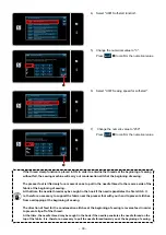
JUKI PLC-2760NVM Скачать руководство пользователя страница 41

– 39 –

<Mode screen>

  Confirming the data entered

Confirm  the  counter  content. Then,  press 


(or 

 if 


 is not displayed) to return the 

screen to the mode screen.

When the screen returns to the sewing screen, the 
content of the counter you have selected is displayed 
on customize button 


.

If you want to use both the sewing counter and the 
bobbin thread counter, press 


 to 

change over the counter display. 
If you press and hold down 


, the 

counter current value screen will be displayed.
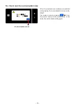
<Sewing screen>

<Bobbin thread counter current value screen>

<Current counter value screen>

When close button 

 is pressed on the mode 

screen, the screen returns to the sewing screen.

Содержание PLC-2760NVM

Страница 1: ...PLC 2760NVM INSTRUCTION MANUAL...

Страница 2: ...4 Needle sway Adjusting the bottom feed amount 20 15 Tension correction 21 15 1 Tension correction and sewing speed 22 15 2 Tension correction and remaining amount of bobbin thread 23 16 Thread clamp...

Страница 3: ...registered Cycle sewing pattern 9 patterns Custom pitch pattern 20 patterns Condensation custom pattern 9 patterns 15 Thread take up Link thread take up 16 Needle bar stroke 40 mm 17 Amount of the alt...

Страница 4: ...of the machine be sure to start the following work after turning the power off and ascertaining that the motor is at rest 2 Threading the machine head Thread the machine head following the order as i...

Страница 5: ...up thread guide The position where take up thread guide is at its lower end while the setscrew is fitted in the upper tapped hole C in the thread guide mounting plate See the figure on the left If you...

Страница 6: ...3 Attach mounting plate on the undersurface of the table with accessory screws supplied with the plate 4 Connect the 6 air tube to joint Screw which is supplied with the unit Thread diameter M5 Length...

Страница 7: ...ble with accessory screw SK3452001SE 2 Connect the 6 tube described in step 4 in 1 Installing the regulator to joint Cut the 6 tube to an appropriate length before use 3 Connect the 4 air tube coming...

Страница 8: ...The Incidental device setting screen is dis played When the device setting of which is to be changed is selected the setting screen for the selected device is displayed 4 Select 1 Center guide to disp...

Страница 9: ...e S056 center guide 10 Then set the ON OFF status of the center guide 11 Press to confirm the value you have entered 12 Press to display the sewing screen If the pneumatic center guide does not functi...

Страница 10: ...er guide Assign the switching function of the center guide to the 6 gang switch 1 held pressed for three second The mode screen is displayed 2 Select 19 Optional I O setting 3 Select 1 Optional input...

Страница 11: ...input 6 Press to confirm the selection 5 3 Setting the optional output for the center guide 1 Select 2 Optional output setting 2 Select OUTPUT11 Function is not provided 3 Select o25 Center guide 4 Pr...

Страница 12: ...ase opening lever crank 6 Move inner hook guide up and down to make sure that there is not play in the thrust direction WARNING To protect against possible personal injury due to abrupt start of the m...

Страница 13: ...rts to move from the position farthest from the protruding portion C of inner hook At this time tighten setscrew of opener cam in such a way that a clearance of 0 2 to 0 5 mm is provided between the t...

Страница 14: ...s upper dead point After you have adjusted the origins of the motors main motor feed motor presser motor and alternating vertical movement motor correct the reference angle of the main motor Angle dis...

Страница 15: ...60 For example enter 5 if the angle you have checked in Step 3 is 5 Enter 8 if the angle you have checked is 352 7 Press to confirm the value you have entered 8 Enter the Hook timing adjustment mode C...

Страница 16: ...state that the moving knife driving arm link is in contact with the roller Then tighten three setscrews of the thread trimmer solenoid mounting plate 4 Raise the sewing machine WARNING To protect aga...

Страница 17: ...am and the cam roller come in contact with each other adjust the distance between the tip of counter knife and the tip of moving knife to 1 3 0 1mm 4 Tighten clamping screw s 1 needle machine One piec...

Страница 18: ...at rest 1 Loosen clamp spring setscrew 2 Move moving knife to the position where it does not come in contact with clamp spring 3 Slide clamp spring while keeping it pressed against the end face of co...

Страница 19: ...feed cam in such a way that needle throat plate and feed dog are positioned as shown in the figure on the left 6 Tighten vertical feed cam setscrews two pieces Conditions Amount of feed 6 mm Alternat...

Страница 20: ...l movement of the walking foot and presser foot to 3 0 on the alternating vertical movement amount screen The PLC 2710V 7 and the PLC 2760V 7 have different displays WARNING To protect against possibl...

Страница 21: ...such a way that needle throat plate walking foot and feed dog are positioned as shown in the figure on the left 7 Tighten top feed cam setscrews two pieces 8 Attach the top cover in place Conditions...

Страница 22: ...arker line C of bottom feed connecting triangle lever Standard When Adjust the position of hinge screw nut of the horizontal feed rear arm in the direction of arrow A the bottom feed amount is decreas...

Страница 23: ...ad remaining amount Both the sewing speed and the bob bin thread remaining amount 4 Select the type of the tension correction data In case of correcting the tension in accor dance with the sewing spee...

Страница 24: ...e set by pressing As in the case of 2 the sewing machine is able to perform sewing at the maximum sewing speed of 1000 sti min 4 When is selected the correction value to be employed when the sewing ma...

Страница 25: ...io of the needle thread ten sion The set value can be reset to the initial value of 100 by pressing 3 When is pressed the entered val ue is confirmed and the screen is returned to the S113 Needle thre...

Страница 26: ...s 0 zero For the section from 70 to 0 the correction along the inclination of the line chart is applied The bobbin counter starts counting down from the target value 200 When it reaches 140 the needle...

Страница 27: ...ssively tighten the setscrew to prevent the solenoid from being deformed 4 Install nipper thread guide and take up thread guide B to the machine arm Remove the top cover face plate handwheel and motor...

Страница 28: ...d cord through the cable clips and re secure the cable clips with the setscrews Bundle the cords with a cable clip band small 9 Bundle the cords with the cable clip band small 10 Connect the thread cl...

Страница 29: ...three loca tions together with other cords 12 Connect the connector of the thread clamp sole noid junction cable asm to the PCB Install the top cover face plate handwheel and motor cover in place Whe...

Страница 30: ...eginning of sewing 4 Select U285 Thread clamp function When you use the thread clamp device make the following settings If the thread clamp device is placed in ON the sewing machine will carry out con...

Страница 31: ...29 5 Select ON Press to confirm the setting 1 Press 2 Select 1 Memory switch 2 Setting the items that are related to the beginning of sewing 3 Select 2 Beginning of sewing...

Страница 32: ...the needle thread to the reverse side of the fabric at the beginning of sewing At that time the needle thread may be caught in the hook if the needle penetrates the first stitch It is therefore neces...

Страница 33: ...to use the thread clamp function set the Thread clamp function while the presser foot is in its up per position to ON 1 Press and hold 2 Select 1 Memory switch 3 Press 5 During stopping 4 Press K141 T...

Страница 34: ...and eccentric roll ers to remove hook cover 2 Remove throat plate setscrews to remove throat plate 3 Loosen moving knife base setscrews to remove moving knife base When removing moving knife base tur...

Страница 35: ...hen you turn eccentric rollers Adjust eccentric rollers on both the front and back sides 4 Loosen counter knife base setscrew to remove counter knife base When removing counter knife base turn the han...

Страница 36: ...pan and secure it in groove Secure reflux pipe as shown in the figure 2 Secure filter and filter holder with metal fittings A OIL_FILTER_A Fit the notch of the filter in the rib on the oil pan OIL_FI...

Страница 37: ...urrent value every time the sewing machine sews 10 stitches When the preset value is reached the count completion screen is displayed Refer to 6 3 4 How to reset the count completion state p 81 in the...

Страница 38: ...g screen 19 3 How to set the counter Selecting the counter setting 2 Select the 4 Counter setting Mode screen Setting the type of counter current value of counter and preset value for counter 1 Displa...

Страница 39: ...numeric keypad 3 Press to confirm the type of counter you have selected Current counter value screen 1 Select the counter set value 2 Enter with the numeric keypad 3 Press to confirm the type of coun...

Страница 40: ...time the sewing machine sews one stitch shape When the current value reaches the preset value the count completion screen is displayed DOWN counter subtracting method The counter subtracts one from it...

Страница 41: ...you have selected is displayed on customize button If you want to use both the sewing counter and the bobbin thread counter press to change over the counter display If you press and hold down the cou...

Страница 42: ...ount completion state When the predetermined conditions are satisfied during sewing the count completion screen is dis played The counter is reset by pressing Then the mode is returned to the sewing m...

Отзывы: