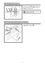
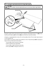
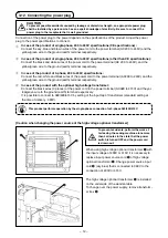
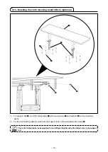
background image

– 9 –

5. OPERATION

5-1. Sewing procedure

)  Press ON button 

1

 of the power swtch to turn 

ON the power.

When the buzzer is kept beeping imme-
diately after turning ON the power, press 
OFF button 

2

 on the sewing machine to 

turn OFF the power since connection of 
the cord or power voltage may be wrong.

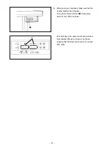
Indication given after turning the power on

)  After the power to the machne s turned on, the 

ndcaton shown below appears on the opera-
ton panel.


The setting item "SEM" flashes on and off.

The machine will not start as long as the lamp 

flashes on and off. If this indication does not 

appear on the operation panel, turn off the 

power to the machine. If the machine head is 

not selected correctly, the indication will not 

appear on the operation panel. 

Refer to the Engineer's Manual for details.

1

2

3

4

Fig. A

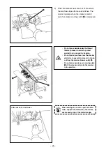
3)  When 

3

 is pressed while it is flashing on and 

off, the machne gets ready for sewng. Insert 
the materal along the cloth gude from the drec-
ton of the arrow as shown n Fg. A.


When the materal s nserted on start sensor 

4


located ths sde of the throat plate, the machne 
starts runnng to perform sewng.

CAUTION :

•  Never start the machine with the eye protector cover raised in order to prevent injury accidents 

caused by the needle and the knife.

•  The machine becomes hot when it is running continuously or after it has run, never touch the 

sewing machine.

Never remove the cloth guide while the 
machine is ready for sewing in order to 
prevent accidents caused by abrupt start 
of the machine.

Содержание ASN-690

Страница 1: ... ENGLISH ASN 690 INSTRUCTION MANUAL ...

Страница 2: ...al 14 4 PREPARATION 15 4 1 Caution before operation 15 4 2 Lubrication 15 4 3 Threading the machine 16 4 4 Adjusting the pressure of the presser foot and removing the presser foot 17 4 5 Adjusting the stitch length 17 4 6 Differential feed mechanism 18 5 OPERATION 19 5 1 Sewing procedure 19 5 2 Explanation of the operation panel 22 5 3 Description of the pedals and the switches on the machine head...

Страница 3: ...eedles 39 7 6 Drainage of filter regulator 39 7 7 Cautions for the compressed air supply source of supply air facility 40 7 8 Dust collector box 41 7 9 Cleaning the sensor 41 7 10 Consumable parts to be replaced 42 7 11 Replacing the fuse 43 7 12 Adjusting the belt tension 44 7 13 Destination of connection for input output connectors 45 7 14 Error codes 46 7 15 Error code list 47 ...

Страница 4: ...vers B Stacker unit C Sub table D Cloth plate E Sewing machine head F Cloth guide G Control box H Sewing machine motor I Start switch for the stacker J Stacker cloth guide K Side cutter L Dust collector M Pneumatic controller N Power switch O Starting pedal for the sewing machine P Thread trimmer presser Q Cloth feeding air blow R Pause switch A B C D O E G N Q H J K M L F I R P ...

Страница 5: ...length Limited to one 12 Number of pieces that can be stacked 70 slacks 13 Power consump tion 590VA or less operating rate 50 14 Pneumatic pres sure 0 5MPa 15 Air consumption 250dm3 min ANR 16 Lubricating oil JUKI MACHINE OIL 18 17 Dimensions Type Width Length Height Short table type 790mm 575mm 875mm 2 880mm Long table type 1500mm 1800mm 2 790mm 880mm 18 Mass of the ma chine Short table type 110k...

Страница 6: ...g which secures the power cable Remove the tape which secures the cloth plate Remove the string which secures the hose 3 2 Securing the machine 1 CAUTION To avoid possible personal injuries be sure to move the machine to a level and stable place and lock casters 1 ...

Страница 7: ...nit as shown in the figure Configuration position differs depending upon speci fication Short table type Long table type When dumping dust from the dust collec tion box also clean up filter 4 Confirm that the hose mounting bracket 5 is completely tightened the same for other mounting hardware Note that the noise muffler 6 is optional 1 5 6 1 2 3 4 5 If the dust collector is not securely in stalled...

Страница 8: ...lt 3 to make the support rod of the stacker parallel to the installing plane 3 Connect air tube 4 to joint 5 and air tube 6 to joint 7 in numerical order 1 2 3 7 5 6 4 CAUTION Be sure to carry out installation of the stacker by two or more workers in order to protect against accidents caused by the stacker unit when it accidentally falls ...

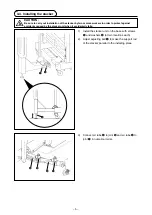
Страница 9: ...cloth guide Installing stacker cloth guide 1 on the guide base with hand screw 2 and washer 3 1 3 2 Material feeding direction 4 Adjust the orientation of the cloth guide according to the clamping position at the stacker unit 4 1 ...

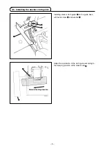
Страница 10: ...chine table 2 Put the slots at two locations in the cloth guide unit as illustrated in the figure over two studs 1 at two locations of the cloth plate over Fix the studs 1 with washer 3 and thumb screws 2 3 Connect air tube 4 to joint 5 Installing position 1 Cloth plate 5 4 Cloth guide unit 2 2 3 3 ...

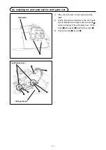
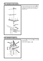
Страница 11: ...washer placed between them and fix with the nut and washers from under the table as illustrated in the figure at left 1 Washer Washer Spring washer Nut 3 8 Installing the regulator Fix regulator 1 on mounting plate 2 with screws 3 at two locations Connect φ8 air tube 4 to joint 5 2 1 3 4 5 ...

Страница 12: ...junction connec tor 4 coming from control box 3 3 9 Connecting the air coupler Connect the air coupler 1 supplied with the unit as an accessory firstly to air hose 2 secondly to cou pler 3 on the main body side Make sure that the pressure gauge of the regulator reads 0 5 MPa 2 1 3 1 2 4 3 ...

Страница 13: ... taking care not to allow your fingers caught between them A difference in height between the top face of the main body table and that of the sub table may be observed on some installation site If such a difference is observed adjust so that the tables are same in height with spacers 4 for adjusting the height of the clips Three spacers are supplied If the sub table is lower than the main body tab...

Страница 14: ... casters at six locations to adjust the height of the sub table to that of the main body table and tighten the screws 5 5 5 5 Sub table Main body table If the difference in height between the sub table and the main body table cannot be eliminated with spacer 4 adjust the height of the main body table or the height of the sub table 5 To protect against possible personal injury or death be sure to c...

Страница 15: ...roduct of 3 phase 200 to 240V specifications Connect the red white and black wires of the power cord to the power terminal AC200 to 240V and the yellow green wire to the ground earth terminal respectively 4 In case of the product with the optional high voltage transformer Connect the black wires 3 pieces of the power cord to the power terminal AC380 to 415V and the yel low green wire to the ground...

Страница 16: ...loth holding table 1 with wood screws 3 and washers 4 at four locations each 2 Fix the cloth holding table mounted with the support rods on the sub table with screws 5 The cloth holding table can be adjusted to four different heights using the fixing holes in the support rod 1 3 2 4 5 5 ...

Страница 17: ...fferential feed switch As long as this switch is held depressed the differential feed function works 2 Pause switch As long as this switch is held depressed the pause function works The machine returns to the normal operation running by releasing the switch 3 High low speed changeover switch Changeover from the high speed to low speed can be done only by a depress on this switch The machine return...

Страница 18: ...ck to be sure that the voltage has been correctly set Make sure that the power plug is connected properly Never use the machine under a voltage that is different from the specification Lubrication to chain off thread trimming device Remove screw 1 from the top end of the oil hose at the rear section of the machine The upper limit of the oil quantity is at the top of the pipe holder Oil consumption...

Страница 19: ...ound the intermediate thread guide How to remove the cloth plate Remove the cloth plate by holding the cloth plate guide base Do not touch the curve sensor optional mounted on the cloth plate How to thread the needle thread silicon oil tank When the needle cooler is used Pass the thread under the center pawl When the needle cooler is not used Pass the thread above the center pawl ...

Страница 20: ...urn the handwheel as you keep depress ing pushbutton 1 and you will find a point at which the pushbutton goes in farther 2 With the above condition maintained align the desired scale mark on the handwheel with mark 2 on the belt cover 3 Reset the pushbutton 1 after setting the dial 1 2 4 5 Adjusting the stitch length CAUTION To protect against possible personal injury due to abrupt start of the ma...

Страница 21: ... ratio of 1 0 8 When the lever is set to graduation 0 the differ ential feed ratio between the main feed dog and the differential feed dog will be 1 1 4 The maximum differential feed ratio for gather ing is 1 2 The graduations beyond 0 are used as standard 5 After the adjustment securely tighten locknut 2 2 3 1 CAUTION To protect against possible personal injury due to abrupt start of the machine ...

Страница 22: ...he machine head is not selected correctly the indication will not appear on the operation panel Refer to the Engineer s Manual for details 1 2 3 4 Fig A 3 When 3 is pressed while it is flashing on and off the machine gets ready for sewing Insert the material along the cloth guide from the direc tion of the arrow as shown in Fig A When the material is inserted on start sensor 4 located this side of...

Страница 23: ...eral stitches The stacker operates when the stacker selector switch or stacker starting switch 5 is depressed 5 Do not place hands under the thread trimmer presser in order to protect against injury caused by trapping Do not place your face near the stacker while it is in operation since air is blown out from the stacker blower outlet 6 Do not place hands near receiving plate 7 of the stacker unit...

Страница 24: ...at the sewing machine has stopped Then press the OFF button 8 of the power switch to turn OFF the power Four dots A in the numeral indicating window momentarily light up as shown in the figure showing that the state has moved to the power OFF state ...

Страница 25: ...this switch is pressed the contents of the display increase If the power to the machine is turned off before having taken the aforementioned procedure the data changed will not be stored in memory 5 Set item indication Abbreviation of the name of the set item selected is displayed 6 Set contents indication Content of the set item selected is displayed 7 Material edge sensor indication It lights up...

Страница 26: ...ctivating the stacker The stacker works regardless of the use disuse setting of the stacker 3 Pause switch When the switch is pressed E050 is displayed on the operation panel to stop the machine After the machine has stopped the machine is restored to the on state by pressing the panel switch 4 Cloth plate open close switch When this switch works E302 is displayed on the operation panel to stop th...

Страница 27: ...900 ms 2 15 S T P 5 5 Number of delay stitches for stopping the machine 0 to 999 stitches 1 16 A U T 1 Setting of the start mode 0 to 1 2 17 C U b 1 Curve mode setting 0 to 1 1 18 C S H 1 Curve differential feed mode setting 0 to 1 1 19 C S S 0 Setting of the number of stitches for starting the curve mode 0 to 999 stitches 1 20 C S E 5 0 Setting of the number of stitches for ending the curve mode ...

Страница 28: ...ast seam Setting range 0 to 99 stitches 5 5 Details of selected functions Current seam the ordinal position of the seam being sewn with respect to the set number of stitches is indicated Set value setting range 1 9 Setting range 0 to 9999 5 Setting of the number of delay stitches for the stacker presser level 2 The number of stitches to be sewn before the stacker presser works after the thread tri...

Страница 29: ...tops is set Setting range 200 to 8000 sti min 3 Setting the speed of stitch for producing chain off thread level 2 The speed of stitch to be employed when operating the chain off thread starting pedal Setting range 200 to 8000 sti min 4 Setting of the start delay time level 2 The time to be elapsed before starting the machine after the material has been detected is set Setting range 0 to 9900 ms 9...

Страница 30: ...o 999 stitches 1 The number of stitches for sucking chain off thread at the beginning of sewing level 2 The number of stitches for sucking chain off thread at the beginning of sewing is set Setting range 0 to 999 stitches 2 Curl blow output time level 2 The time to be elapsed before turning off the curl blow after the machine has stopped is set Setting range 0 to 60 seconds 3 Presser foot lift wai...

Страница 31: ...the time of one second or more has passed If ON OFF operation of the power is performed quickly setting may be not changed over well 2 Auto lifter is not actuated unless this function is properly selected All contents of function setting of the control box can be returned to the standard set values 1 Pressing all switches 1 2 and 3 turn ON the power switch 2 LED displays indication 4 with the soun...

Страница 32: ... the stacker height Loosen nuts 1 at two locations and adjust the orientation of the stacker unit 2 2 Adjusting the orientation of the stacker 6 ADJUSTMENT If the stacked materials are not neatly stacked adjust the orientation of the stacker unit so that stacker support board 2 is at right angles to the stacker cloth guide material feeding direction Material feeding direction 2 CAUTION To avoid po...

Страница 33: ...blow optional 2 The air blowing amount is reduced by turning the adjusting knob clockwise 3 The air blowing direction of the cloth feeding blow can be changed by loosing the M4 nut mounted underside of the table After changing the air blowing direction be sure to tighten the nut to fix it In addition check to be sure that the air hoses are fully tightened with a clip band 1 2 3 When adjusting fix ...

Страница 34: ...sing screws 2 2 Curl guide 3 works to prevent the material edge from curling Adjust the curl guide with screw 4 according to the cloth thickness 6 4 Adjusting the edge guide CAUTION Turn OFF the power before starting the work so as to prevent accidents caused by abrupt start of the sewing machine 3 1 2 4 Overedging width of the material Material 3 ...

Страница 35: ...direction shown by arrow After the adjustment of overedging width of the material with edge guide 4 adjust the surface of edge guide 4 and that of cloth guide 3 Fig A are flush with each other 2 If the knob 1 is turned to the right cloth guide 3 is lowered and if the knob is turned to the left cloth guide is raised Make adjustment ac cording to the cloth thickness 6 5 Adjusting the cloth guide CAU...

Страница 36: ...djusting the cloth chip suction force The suction force for the cloth chip collec tor and the dust collector mounted on the upper looper bracket is adjusted by means of the same adjusting screw 1 CAUTION Turn OFF the power before starting the work so as to prevent accidents caused by abrupt start of the sewing machine ...

Страница 37: ... therefore necessary to adjust the sensitivity of the amplifier Amplifier 1 for the start sensor is located on the control box Amplifier 2 for the curve sensor is located at the rightmost position on the top face of the cloth plate 1 2 6 8 Adjusting the sensors Main digital display indication in red The amount of light received is displayed Sub digital display indication in green The threshold is ...

Страница 38: ... the operation panel 5 The sensitivity adjustment is completed and the turning indicator lamp lights up 6 The adjustment is completed and the power tun ing indicator lamp lights up Close the sensor amplifier cover 3 seconds MODE Amount of light received Threshold setting at the time of delivery PTUN Progress bar Target value for the power tuning Indication automatically changes at predetermined in...

Страница 39: ... setting procedure 8 Place the SET RUN changeover switch in RUN 9 The setting procedure is completed and the indication returns to the one given before the operation Close the sensor amplifier cover 10 Insert the material into the cloth guide unit Check to be sure that the amount of light re ceived do not exceed the threshold Press one of them for one second DOWN TECH Amount of light received Thre...

Страница 40: ... work after turning the power off and ascertaining that the motor is at rest To protect against possible personal injury never touch the blade of the knife with fingers and hands To prevent possible accidents caused by inexperienced persons and those resulting from maladjustment adjustment work should only be carried out by maintenance personnel who have received safety training and are familiar w...

Страница 41: ...components or replace cartridge filter 1 4 Re insert cartridge filter 1 into its proper posi tion and return the cover Do not forget to put back the setscrews and tighten them up 2 How to inspect the cartridge filter and replace it 1 Remove first oil discharging screw 2 2 Remove screws 3 and lift top cover 4 just above until it comes off 1 Use JUKI MACHINE OIL 18 in the machine head 2 To change th...

Страница 42: ...o use the DC 1 needle In this case however the clearance provided between the needle and the looper may be required to be adjusted If sewing need to be carried out with a finely adjusted thread tension use the DC 27 needle 1 Bring needle clamp 1 to the highest position 2 Loosen needle clamp screw 2 and fully insert the needle into the needle clamp hole with the needle recess facing backwards as vi...

Страница 43: ...ality of the air supply When the supply air contains a considerable amount of moisture Ambient environment When our machine is installed at a place where the temperature greatly changes in the morning and in the evening from that in the daytime or freeze is like to occur In the aforementioned cases be sure to install an air dryer Most troubles in the air solenoid valves are caused by carbon Be sur...

Страница 44: ...ting point 5 for the start sensor on the rear face of the cloth plate Remove the cloth plate to carry out the dust removal procedure 7 9 Cleaning the sensor CAUTION Turn OFF the power before starting the work so as to prevent accidents caused by abrupt start of the sewing machine 1 Throw away waste cloth chips inside the dust collector box at least once a day At this time also clean up the filter ...

Страница 45: ...thread trimming at the end of sewing Side cutter block Thread trimmer presser sponge The following parts are consumables Be sure to periodically replace them with new ones CAUTION Turn OFF the power before starting the work so as to prevent accidents caused by abrupt start of the sewing machine To protect against possible personal injury never touch the blade of the knife with fingers and hands To...

Страница 46: ...OFF button of the power switch to turn OFF the power after confirming that the sewing machine has stopped 2 Draw out the power cord coming from the power plug socket after confirming that the power switch is turned OFF Perform the work of step 3 after confirming that the power has been cut and it has passed for 5 minutes or more Be sure to open close the front cover 1 with your hands Replacing F1 ...

Страница 47: ...ith a fuse of the same capacity supplied as accessories 6 Fix the bottom cover as before with the set screws and press the front cover to the bottom cover from the position where the front cover is obliquely tilted by approximately 45 degrees for assembling 7 Attach the connectors and the ground wire which have been removed 8 Close the front cover as before and fix it with the setscrews while payi...

Страница 48: ...ut output supply voltage W3 W4 0 CN50 Connector for solenoid valve Refer to the Engineer s Manual for details 1 CN51 Connector for sensor switch Refer to the Engineer s Manual for details 2 CN41 Connector for expansion board unused 3 W5 to W8 Jumper for changing over CN51 input unused If the connection is changed the signal will not input properly 4 CN39 Connector for pedal junction cable 5 CN201 ...

Страница 49: ...ter the existing error code is displayed Phenomenon Cause Corrective measure When tilting the sewing machine the buzzer beeps and the sewing ma chine cannot be operated When tilting the sewing machine without turning OFF the power switch action given on the left side is taken for safety sake Tilt the sewing machine after turning OFF the power Solenoids for thread trimming re verse feed wiper etc f...

Страница 50: ...ly set Check whether fuse or regenerative resis tance is broken E924 Motor driver failure Motor driver has broken No Description of error detected Cause of occurrence expected Items to be checked E000 Execution of data initialization This is not the error When the machine head is changed When the initialization operation is executed E003 Disconnection of synchro nizer connector When position detec...

Отзывы: