


GLOSSARY
xxiii
GLOSSARY
This section describes the main terms used for this equipment and general related
maritime terms.
A
AZ
Acquisition/Activation zone
A zone set up by the operator in which the system should automatically acquire radar
targets and activate reported AIS targets when entering the zone.
Activated target
A target representing the automatic or manual activation of a sleeping target for the
display of additional information.
AIS
Automatic Identification System
A system which enables ships and shore stations to obtain identifying and navigation
information about other ships at sea, using an automated transponder.
Anti-clutter rain
Rain/snow clutter suppression.
Anti-clutter sea
Sea clutter suppression.
AZI
AZImuth stabilization mode
B
BCR/BCT
Bow Crossing Range and Bow Crossing Time
C
C up
Course up
Own ship’s course is pointed to the top center of the radar display.
CCRP
The Consistent Common Reference Point
A location on own ship, to which all horizontal measurements such as target range,
bearing, relative course, relative speed, CPA or TCPA are referenced, typically the
conning position of the bridge.
Clutter
Unwanted reflections on a radar screen, from sea surface, rain or snow.
COG
Course Over Ground
The direction of the ship's movement relative to the earth, measured on board the ship,
expressed in angular units from true north
CORREL
Correlation
CPA/TCPA
The distance to the Closest Point of Approach and Time to the Closest Point of
Approach. Limits are set by the operator and are related to own ship.
CTW
Course Through Water
The direction of the ship's movement through the water
D
DRIFT
The current velocity for manual correction or the current speed on the horizontal axis of
the 2-axis log is displayed.
Содержание JMA-3300 Series
Страница 2: ......
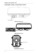
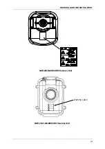
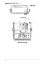
Страница 16: ...WARNING LABEL MOUNTING POINT xiv NCD 2182 Display Unit ...
Страница 17: ...WARNING LABEL MOUNTING POINT xv NBA 5111 Power Supply NBD 865 Rectifier unit ...
Страница 30: ...GLOSSARY xxviii ...
Страница 46: ...Chapter 1 GENERAL AND EQUIPMENT COMPOSITION 1 5 GENERAL SYSTEM DIAGRAMS 1 16 ...
Страница 47: ...Chapter 2 OPERATIONS 2 1 SCREEN DISPLAY 2 1 2 INSTRUCTION MANUAL Chapter 2 OPERATIONS 2 1 SCREEN DISPLAY ...
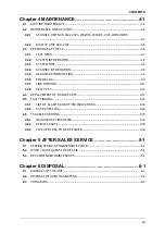
Страница 244: ...Chapter 4 MAINTENANCE 4 6 TROUBLE SHOOTING 4 36 ...
Страница 254: ...Chapter 7 SPECIFICATIONS 7 2 SCANNER 7 6 13 Overall Noise Figure 6dB Average 14 Tune AUTO MANUAL ...
Страница 265: ...APPENDIX APPENDIX 1 APPENDIX INSTRUCTION MANUAL APPENDIX Fig A1 NKE 2042 SCANNER INTERCONNECTION DIAGRAM ...
Страница 266: ...APPENDIX APPENDIX 2 Fig A2 NKE 2043 SCANNER INTERCONNECTION DIAGRAM ...
Страница 267: ...APPENDIX APPENDIX 3 APPENDIX INSTRUCTION MANUAL Fig A3 NKE 2062 SCANNER INTERCONNECTION DIAGRAM ...
Страница 268: ...APPENDIX APPENDIX 4 Fig A4 NKE 2062HS SCANNER INTERCONNECTION DIAGRAM ...
Страница 269: ...APPENDIX APPENDIX 5 APPENDIX INSTRUCTION MANUAL Fig A5 NKE 2063 SCANNER INTERCONNECTION DIAGRAM ...
Страница 271: ...APPENDIX APPENDIX 7 APPENDIX INSTRUCTION MANUAL LJ 1 6 6 11 5 17 5 211 7 21 5 0 ...
Страница 272: ...APPENDIX APPENDIX 8 Fig A8 NKE 2063AHS SCANNER INTERCONNECTION DIAGRAM ...
Страница 273: ...APPENDIX APPENDIX APPENDIX INSTRUCTION MANUAL Fig A NKE 2103 4 4HS 6 6HS SCANNER INTERCONNECTION DIAGRAM ...
Страница 274: ...APPENDIX APPENDIX Fig A NCD 2182 DISPLAY UNIT INTERCONNECTION DIAGRAM ...
Страница 275: ...APPENDIX APPENDIX APPENDIX INSTRUCTION MANUAL Fig A PRIMARY POWER SUPPLY DIAGRAM TYPE JMA 3300 6 6 6 ...
Страница 276: ...APPENDIX APPENDIX 1 Fig A1 JMA 3314 INTERCONNECTION DIAGRAM ...
Страница 277: ...APPENDIX APPENDIX 1 APPENDIX INSTRUCTION MANUAL Fig A1 JMA 3334 INTERCONNECTION DIAGRAM ...
Страница 278: ...APPENDIX APPENDIX 1 Fig A1 JMA 3316 HS INTERCONNECTION DIAGRAM ...
Страница 279: ...APPENDIX APPENDIX 1 APPENDIX INSTRUCTION MANUAL Fig A1 JMA 3336 HS INTERCONNECTION DIAGRAM NKE 2063 A HS AHS ...
Страница 280: ...APPENDIX APPENDIX 1 Fig A1 JMA 3340 4 4HS 6 6HS INTERCONNECTION DIAGRAM ...
Страница 297: ......