


PRECAUTIONS
viii
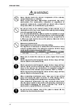
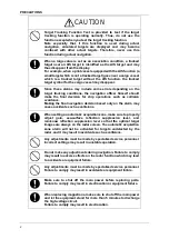
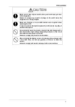
WARNING
Never directly touch the internal components of the antenna,
receiver/transceiver, or indicator.
Direct contact with these high-voltage components may cause
electrocution. For maintenance, inspection, or adjustment of
equipment components, consult with our branch office, branch
shop, sales office, or our distributor in your district.
Do not get close to the radiant section of the antenna. It is a
rotating part, and it may cause injuries if it suddenly starts rotating
and consequently hits the body.
It is recommended that the radiant section be installed at a high
place such as on the roof of the wheelhouse, on the flying bridge,
on the trestle, or on the radar mast so that no one can get close to
it. When any work must be done on the antenna, make sure to turn
the antenna switch off.
Microwave radiation level:
Keep away from a scanner when it is transmitting.
The high level of microwave is radiated from the front face of the
scanner specified below. The microwave exposure at close range
could result in injuries (especially of the eyes).
50W/m
2
10W/m
2
2.5W/m
2
NKE-2103
n/a
26cm
123cm
Make sure to install the antenna at a place higher than human
height.
Direct exposure to electromagnetic waves at close range will have
adverse effects on the human body.
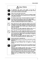
Direct exposure to electromagnetic waves at close range will have
adverse effects on the human body. When it is necessary to get
close to the antenna for maintenance or inspection purposes,
make sure to turn the indicator power switch to "OFF" or "STBY."
Direct exposure to electromagnetic waves at close range will have
adverse effects on the human body.
When conducting maintenance work, make sure to turn off the
power and unplug the power connector J1 of the display unit so
that the power supply to the equipment is completely cut off.
Some equipment components can carry electrical current even
after the power switch is turned off, and conducting maintenance
work without unplugging the power connector may result in
electrocution, equipment failure, or accidents.
Do not touch the radiator. Even if the power is turned off, the
radiator may be rotated by the wind.
Содержание JMA-3300 Series
Страница 2: ......
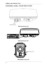
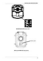
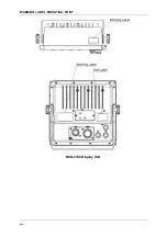
Страница 16: ...WARNING LABEL MOUNTING POINT xiv NCD 2182 Display Unit ...
Страница 17: ...WARNING LABEL MOUNTING POINT xv NBA 5111 Power Supply NBD 865 Rectifier unit ...
Страница 30: ...GLOSSARY xxviii ...
Страница 46: ...Chapter 1 GENERAL AND EQUIPMENT COMPOSITION 1 5 GENERAL SYSTEM DIAGRAMS 1 16 ...
Страница 47: ...Chapter 2 OPERATIONS 2 1 SCREEN DISPLAY 2 1 2 INSTRUCTION MANUAL Chapter 2 OPERATIONS 2 1 SCREEN DISPLAY ...
Страница 244: ...Chapter 4 MAINTENANCE 4 6 TROUBLE SHOOTING 4 36 ...
Страница 254: ...Chapter 7 SPECIFICATIONS 7 2 SCANNER 7 6 13 Overall Noise Figure 6dB Average 14 Tune AUTO MANUAL ...
Страница 265: ...APPENDIX APPENDIX 1 APPENDIX INSTRUCTION MANUAL APPENDIX Fig A1 NKE 2042 SCANNER INTERCONNECTION DIAGRAM ...
Страница 266: ...APPENDIX APPENDIX 2 Fig A2 NKE 2043 SCANNER INTERCONNECTION DIAGRAM ...
Страница 267: ...APPENDIX APPENDIX 3 APPENDIX INSTRUCTION MANUAL Fig A3 NKE 2062 SCANNER INTERCONNECTION DIAGRAM ...
Страница 268: ...APPENDIX APPENDIX 4 Fig A4 NKE 2062HS SCANNER INTERCONNECTION DIAGRAM ...
Страница 269: ...APPENDIX APPENDIX 5 APPENDIX INSTRUCTION MANUAL Fig A5 NKE 2063 SCANNER INTERCONNECTION DIAGRAM ...
Страница 271: ...APPENDIX APPENDIX 7 APPENDIX INSTRUCTION MANUAL LJ 1 6 6 11 5 17 5 211 7 21 5 0 ...
Страница 272: ...APPENDIX APPENDIX 8 Fig A8 NKE 2063AHS SCANNER INTERCONNECTION DIAGRAM ...
Страница 273: ...APPENDIX APPENDIX APPENDIX INSTRUCTION MANUAL Fig A NKE 2103 4 4HS 6 6HS SCANNER INTERCONNECTION DIAGRAM ...
Страница 274: ...APPENDIX APPENDIX Fig A NCD 2182 DISPLAY UNIT INTERCONNECTION DIAGRAM ...
Страница 275: ...APPENDIX APPENDIX APPENDIX INSTRUCTION MANUAL Fig A PRIMARY POWER SUPPLY DIAGRAM TYPE JMA 3300 6 6 6 ...
Страница 276: ...APPENDIX APPENDIX 1 Fig A1 JMA 3314 INTERCONNECTION DIAGRAM ...
Страница 277: ...APPENDIX APPENDIX 1 APPENDIX INSTRUCTION MANUAL Fig A1 JMA 3334 INTERCONNECTION DIAGRAM ...
Страница 278: ...APPENDIX APPENDIX 1 Fig A1 JMA 3316 HS INTERCONNECTION DIAGRAM ...
Страница 279: ...APPENDIX APPENDIX 1 APPENDIX INSTRUCTION MANUAL Fig A1 JMA 3336 HS INTERCONNECTION DIAGRAM NKE 2063 A HS AHS ...
Страница 280: ...APPENDIX APPENDIX 1 Fig A1 JMA 3340 4 4HS 6 6HS INTERCONNECTION DIAGRAM ...
Страница 297: ......