


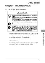


Chapter 4
MAINTENANCE
4.2
MAINTENANCE ON EACH UNIT
4-4
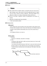
Radiator
Note:
z
If the radiator front face (radiation plane) is soiled with smoke, salt, dust, paint or
birds’ droppings, wipe it with a piece of soft cloth wetted with alcohol or water
and try to keep it clean at all times. Otherwise, radar beam radiation may
attenuate or reflect on it, resulting in deterioration of radar performance.
z
Never use solvents of gasoline, benzine, trichloroethylene and ketone for
cleaning.
Otherwise, the radiation plane may deteriorate.
Check up and clean the radiator.
Rotating section
Oiling gears
Apply grease evenly to the tooth surfaces of the main shaft drive gear and the encoder
drive gear with a spreader or brush. Oiling in short intervals is more effective to prevent
the gears from wear and tear and extend their service life, but oil at least every six
months.
Use the grease of Mobilux 2 of Mobil Oil.
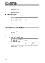
Driving motor
i) Attenuator
Greasing is not necessary unless there is oil leakage.
ii) Motor
The life span of the brush itself is 2000 hours. When the brush is worn out to a half
of the entire length, replace it.
The communicator must be kept clean all the time. If carbon dust is stuck and cannot
be removed with a dry cloth, polish the section with sand paper of No.150 to 400.
The carbon brush can be removed by removing the caps on both sides of the bottom
of the motor.
Carbon brush
Communicator contact side
Spring
Содержание JMA-3300 Series
Страница 2: ......
Страница 16: ...WARNING LABEL MOUNTING POINT xiv NCD 2182 Display Unit ...
Страница 17: ...WARNING LABEL MOUNTING POINT xv NBA 5111 Power Supply NBD 865 Rectifier unit ...
Страница 30: ...GLOSSARY xxviii ...
Страница 46: ...Chapter 1 GENERAL AND EQUIPMENT COMPOSITION 1 5 GENERAL SYSTEM DIAGRAMS 1 16 ...
Страница 47: ...Chapter 2 OPERATIONS 2 1 SCREEN DISPLAY 2 1 2 INSTRUCTION MANUAL Chapter 2 OPERATIONS 2 1 SCREEN DISPLAY ...
Страница 244: ...Chapter 4 MAINTENANCE 4 6 TROUBLE SHOOTING 4 36 ...
Страница 254: ...Chapter 7 SPECIFICATIONS 7 2 SCANNER 7 6 13 Overall Noise Figure 6dB Average 14 Tune AUTO MANUAL ...
Страница 265: ...APPENDIX APPENDIX 1 APPENDIX INSTRUCTION MANUAL APPENDIX Fig A1 NKE 2042 SCANNER INTERCONNECTION DIAGRAM ...
Страница 266: ...APPENDIX APPENDIX 2 Fig A2 NKE 2043 SCANNER INTERCONNECTION DIAGRAM ...
Страница 267: ...APPENDIX APPENDIX 3 APPENDIX INSTRUCTION MANUAL Fig A3 NKE 2062 SCANNER INTERCONNECTION DIAGRAM ...
Страница 268: ...APPENDIX APPENDIX 4 Fig A4 NKE 2062HS SCANNER INTERCONNECTION DIAGRAM ...
Страница 269: ...APPENDIX APPENDIX 5 APPENDIX INSTRUCTION MANUAL Fig A5 NKE 2063 SCANNER INTERCONNECTION DIAGRAM ...
Страница 271: ...APPENDIX APPENDIX 7 APPENDIX INSTRUCTION MANUAL LJ 1 6 6 11 5 17 5 211 7 21 5 0 ...
Страница 272: ...APPENDIX APPENDIX 8 Fig A8 NKE 2063AHS SCANNER INTERCONNECTION DIAGRAM ...
Страница 273: ...APPENDIX APPENDIX APPENDIX INSTRUCTION MANUAL Fig A NKE 2103 4 4HS 6 6HS SCANNER INTERCONNECTION DIAGRAM ...
Страница 274: ...APPENDIX APPENDIX Fig A NCD 2182 DISPLAY UNIT INTERCONNECTION DIAGRAM ...
Страница 275: ...APPENDIX APPENDIX APPENDIX INSTRUCTION MANUAL Fig A PRIMARY POWER SUPPLY DIAGRAM TYPE JMA 3300 6 6 6 ...
Страница 276: ...APPENDIX APPENDIX 1 Fig A1 JMA 3314 INTERCONNECTION DIAGRAM ...
Страница 277: ...APPENDIX APPENDIX 1 APPENDIX INSTRUCTION MANUAL Fig A1 JMA 3334 INTERCONNECTION DIAGRAM ...
Страница 278: ...APPENDIX APPENDIX 1 Fig A1 JMA 3316 HS INTERCONNECTION DIAGRAM ...
Страница 279: ...APPENDIX APPENDIX 1 APPENDIX INSTRUCTION MANUAL Fig A1 JMA 3336 HS INTERCONNECTION DIAGRAM NKE 2063 A HS AHS ...
Страница 280: ...APPENDIX APPENDIX 1 Fig A1 JMA 3340 4 4HS 6 6HS INTERCONNECTION DIAGRAM ...
Страница 297: ......