10-20
middle value lie in the interval 40 – 120. The middle value
shall be stable during the test. The value depends on
transducer load.
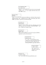
T5 RUN SELFTESTS
DISABLED
Menu T5 forces all built-in self-diagnostic tests to be executed. The A2 DIAG
HISTORY list is cleared at start of test. If any self-test fails a diagnostic code
will be activated.
Use + to change menu to ENABLED and then
Enter
to start the test and go to
next sub-level where the test result will be displayed.
T5.1 NO CODES
IN LIST
Menu T5.1 will continuously show the latest generated
diagnostic code. The list will be cleared upon entering this
menu. Any new code activated as a result of the forced test
(it can take several seconds) will be shown in the order of
appearance.
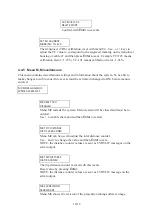
T6 LOGFAIL ALARM
DISABLED
Menu T6 forces the log fail alarm relay to be set from this menu instead of
internal status.
Use + to change menu to ENABLED and then
Enter
to start the test and go to
next sub-level where the relay can be toggled.
T6.1 LFA RELAY
NO ALARM POS.
Menu T6.1 displays the present LFA relay position.
NO ALARM POS. (if relay is not in alarm position) or
ALARM POSITION (if relay is in alarm position)
Use – or + to select desired relay position and then
Enter
to
physically set the relay.
4.4.8 Menu V, View menus
End user and service personnel are intended to use these menus to gather statistics.
Press
Enter
to go into sub-menus. All menus are read only. To interpret the values please refer
to corresponding T menus.
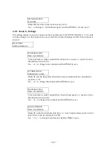
V0 VIEW RECORDED
WRITE ACCESS OFF
Содержание JLN-900
Страница 2: ......
Страница 12: ...x This page is intentionally blank ...
Страница 17: ...2 1 JLN 900 Technical Description ...
Страница 23: ...2 7 sigbel ...
Страница 30: ...2 14 This page is intentionally blank ...
Страница 31: ...3 1 JLN 900 Technical Specification ...
Страница 38: ...3 8 This page is intentionally blank ...
Страница 39: ...4 1 JLN 900 Installation of Transducer and Bottom Parts ...
Страница 49: ...4 11 Overall dimensions of the final installation is shown in Fig 1 2 Fig 1 2 MSSBSV H Main dimensions ...
Страница 59: ...4 21 Transducer and Valve Cover mounted Sea Valve fully opened ...
Страница 63: ...4 25 Fig 1 3 Aligning Transducer Connecting Tube ...
Страница 66: ...4 28 Overall dimensions of the final installation is shown in below Fig 2 2 Fig 2 2 MSDBSV H Main dimensions ...
Страница 76: ...4 38 Mounting Sea Valve on Upper Flange DB ...
Страница 81: ...4 43 Gasket Seal 2 ...
Страница 83: ...4 45 Transducer and Valve Cover mounted Sea Valve fully opened ...
Страница 86: ...4 48 Tube Bracket in its final position with Transducer flush seated ...
Страница 88: ...4 50 Fig 2 5 Aligning Transducer Connecting Tube ...
Страница 92: ...4 54 This page is intentionally blank ...
Страница 93: ...5 1 JLN 900 Installation of NJC 80 Sig Processor ...
Страница 101: ...6 1 JLN 900 NQA 4480 Sig Distributor Technical Manual Incl installation setting up and maintenance guidelines ...
Страница 150: ...6 50 This page is intentionally blank ...
Страница 151: ...7 1 JLN 900 Display Technical Description ...
Страница 167: ...7 17 No Name Default setting Function SD 4 2 SD 4 3 SD 4 4 there are remote systems connected ...
Страница 179: ...8 1 JLN 900 Analog Display Technical Manual ...
Страница 183: ...8 5 2 1 Main Dimensions NWW 828 Analog Display ...
Страница 184: ...8 6 2 2 Dimmer Potentiometer connection Analog Display ...
Страница 186: ...8 8 This page is intentionally blank ...
Страница 187: ...9 1 JLN 900 Menu System ...
Страница 208: ...9 22 This page is intentionally blank ...
Страница 209: ...10 1 JLN 900 WATER TRACK Technical Manual including Menu system ...
Страница 233: ...11 1 JLN 900 IEC 61162 NMEA 0183 User Guide ...
Страница 254: ...11 22 This page is intentionally blank ...
Страница 255: ...12 1 JLN 900 Harbour Acceptance Test ...
Страница 266: ...12 12 This page is intentionally blank ...
Страница 267: ...13 1 JLN 900 Calibration and Sea Acceptance Test ...
Страница 280: ...13 14 This page is intentionally blank ...
Страница 281: ...JLN 900 system drawings 14 1 ...
Страница 289: ...CFT 780 4 TRANSDUCER 40m 14 9 ...
Страница 290: ...NKF 980 Sea Valve 14 10 ...
Страница 291: ...NKF 980 Sea Valve 14 11 ...
Страница 292: ...NWW 82 MAIN DISPLAY 14 12 ...
Страница 293: ...DISPLAY 3 1 87 14 13 ...
Страница 294: ...NCM 1080 DIMMER UNIT 14 14 ...
Страница 295: ...15 1 JLN 900 Description labels and drawings ...
Страница 300: ...15 6 This page is intentionally blank ...
Страница 301: ...16 1 Annex JLN 900 Speed Log System Manual ...
Страница 302: ...16 2 Annex Table of contents ANNEX I EQUIPMENT RECYCLING 3 ANNEX II ENERGY SAVING 5 ...
Страница 306: ...16 6 This page is intentionally blank ...
Страница 307: ......


