6-45
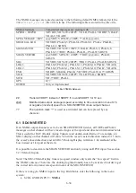
1: LED S2 = OFF (only a few seconds)
2: LED S2 = ON
3: Previous updates will be erased
4: The EPROM will be reset with the factory default menu settings and config.
5: To indicate that the factory reset procedure is finished, LED S2 goes OFF.
The factory reset takes totally about 1 minute and 30 seconds.
The LEDs (S1 and S2) may also indicate if something went wrong, by flashing repeatedly.
Press the Reboot button to try once more. Information about the factory-reset progress is sent to
a Hyper Terminal if connected to the service RS232 D-sub (115k 8N1).
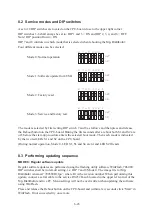
When factory reset is finished, set the DIP switch back to Mode 0 (back to default, move DIP
8=off), normal operation and press and release the Reboot button. After about 45 seconds the
system is up and running.
8.5 USB
Either one of the two USB connections can be used, but not simultaneously.
8.5.1 USB memory stick requirements
The USB memory stick must be formatted with a file system of type FAT32.
Menu S17 can be used to erase and format an inserted USB memory sticks. However, it might
fail depending on Sig. Distributor load and the type of USB memory. If Menu S17 fails, use a
PC to format the USB memory to FAT 32.
8.5.2 Recording NMEA to a USB memory stick
It is possible to store all incoming and outgoing NMEA messages to a USB Memory stick. This
enables long time monitoring of system functionality. The USB memory stick can later be sent
for analysis. All incoming and outgoing NMEA messages are stored in a folder named
LPU2recordings
on the USB memory stick.
1: Insert an empty USB memory stick.
2: Reboot the
Sig. Distributor
using the Reboot button or menu M9.
3: Start the NMEA recording by enabling menu S16. This menu is by default enabled.
If already enabled, the recording will start by itself. The USB memory stick is updated once
every minute. The recording will not overwrite any data when USB memory stick is full.
8.6 Troubleshooting
The Sig. Distributor is equipped with several functions for easy troubleshooting.
x
Fuses
3 pcs 5x20mm 2,5A SB (F101
Ù
230V, F102
Ù
100/115V, F103
Ù
Common,
N) located at the PSU board. These fuses power the Sig. Distributor.
4 pcs 5x20mm 1,6A SB supplying DC out, located at the IO board.
Each of these fuses supplies 3 terminals, i.e. the upper fuse supply terminals 47-
49, the second fuse supply terminals 50-52 etc. Each fuse has a green control
LED to the right of the fuse. At normal operation these four LEDs shall be lit.
Содержание JLN-900
Страница 2: ......
Страница 12: ...x This page is intentionally blank ...
Страница 17: ...2 1 JLN 900 Technical Description ...
Страница 23: ...2 7 sigbel ...
Страница 30: ...2 14 This page is intentionally blank ...
Страница 31: ...3 1 JLN 900 Technical Specification ...
Страница 38: ...3 8 This page is intentionally blank ...
Страница 39: ...4 1 JLN 900 Installation of Transducer and Bottom Parts ...
Страница 49: ...4 11 Overall dimensions of the final installation is shown in Fig 1 2 Fig 1 2 MSSBSV H Main dimensions ...
Страница 59: ...4 21 Transducer and Valve Cover mounted Sea Valve fully opened ...
Страница 63: ...4 25 Fig 1 3 Aligning Transducer Connecting Tube ...
Страница 66: ...4 28 Overall dimensions of the final installation is shown in below Fig 2 2 Fig 2 2 MSDBSV H Main dimensions ...
Страница 76: ...4 38 Mounting Sea Valve on Upper Flange DB ...
Страница 81: ...4 43 Gasket Seal 2 ...
Страница 83: ...4 45 Transducer and Valve Cover mounted Sea Valve fully opened ...
Страница 86: ...4 48 Tube Bracket in its final position with Transducer flush seated ...
Страница 88: ...4 50 Fig 2 5 Aligning Transducer Connecting Tube ...
Страница 92: ...4 54 This page is intentionally blank ...
Страница 93: ...5 1 JLN 900 Installation of NJC 80 Sig Processor ...
Страница 101: ...6 1 JLN 900 NQA 4480 Sig Distributor Technical Manual Incl installation setting up and maintenance guidelines ...
Страница 150: ...6 50 This page is intentionally blank ...
Страница 151: ...7 1 JLN 900 Display Technical Description ...
Страница 167: ...7 17 No Name Default setting Function SD 4 2 SD 4 3 SD 4 4 there are remote systems connected ...
Страница 179: ...8 1 JLN 900 Analog Display Technical Manual ...
Страница 183: ...8 5 2 1 Main Dimensions NWW 828 Analog Display ...
Страница 184: ...8 6 2 2 Dimmer Potentiometer connection Analog Display ...
Страница 186: ...8 8 This page is intentionally blank ...
Страница 187: ...9 1 JLN 900 Menu System ...
Страница 208: ...9 22 This page is intentionally blank ...
Страница 209: ...10 1 JLN 900 WATER TRACK Technical Manual including Menu system ...
Страница 233: ...11 1 JLN 900 IEC 61162 NMEA 0183 User Guide ...
Страница 254: ...11 22 This page is intentionally blank ...
Страница 255: ...12 1 JLN 900 Harbour Acceptance Test ...
Страница 266: ...12 12 This page is intentionally blank ...
Страница 267: ...13 1 JLN 900 Calibration and Sea Acceptance Test ...
Страница 280: ...13 14 This page is intentionally blank ...
Страница 281: ...JLN 900 system drawings 14 1 ...
Страница 289: ...CFT 780 4 TRANSDUCER 40m 14 9 ...
Страница 290: ...NKF 980 Sea Valve 14 10 ...
Страница 291: ...NKF 980 Sea Valve 14 11 ...
Страница 292: ...NWW 82 MAIN DISPLAY 14 12 ...
Страница 293: ...DISPLAY 3 1 87 14 13 ...
Страница 294: ...NCM 1080 DIMMER UNIT 14 14 ...
Страница 295: ...15 1 JLN 900 Description labels and drawings ...
Страница 300: ...15 6 This page is intentionally blank ...
Страница 301: ...16 1 Annex JLN 900 Speed Log System Manual ...
Страница 302: ...16 2 Annex Table of contents ANNEX I EQUIPMENT RECYCLING 3 ANNEX II ENERGY SAVING 5 ...
Страница 306: ...16 6 This page is intentionally blank ...
Страница 307: ......


