13
Installation Procedure
Each PWS comes complete with a pre-assembled main sub-assembly, wall mounting plate and 6-32 mounting
hardware. PWS is designed for installation into standard grounded single gang electrical backboxes.
1. Ensure the electrical back box is grounded to earth ground via dedicated grounding wiring or through conduit
where electrical code permits. An un-grounded box may lead to damage from static electricity and void
warranty.
2. Clean back box of all debris including metal filings, dust, drywall or any other debris that could affect electrical
performance. Compressed air is best for this.
3. Check the back box 6-32” mount threads before attempting to install the wall mounting plate. This can be
easily done be spinning one of the supplied mounting screws clockwise with your fingers into each of the two
mounting holes. They should install easily with your fingers. If they do not, it is recommended to run a 6-32”
drill tap through the hole with a small reversable drill to “clean out” any bad threading.
4. Install the wall mounting plate flush to the wall and tighten with the supplied mounting screws snuggly as to not
deform the plastic but provide a tight fit to the wall. Use a small level to ensure a plumb level installation of the
plate.
DO NOT
overtighten the mounting screws. Hand tightening is recommended over any power assist tool.
Important: DO NOT
exceed 1.5 in. - lbf. for drywall and 5.0 in. - lbf. for Presidor™ Surface Boxes (PSB).
5. Label all wiring as “to or from” for future identification. Dress out all the wiring and terminate to the appropriate
connectors based on installation and PWS model type. Leave at least an 8-12” service loop if possible. Ensure
all wire is stripped back far enough to ensure full plug insertion without insulation. Plug all the terminated
wiring connectors to their final location on the PWS I/O PCB. Tape off or heat-shrink any exposed shield wiring
or unused conductors that could touch the rear of the station and cause a short circuit.
6. Set the dip switches as required for Main/Secondary PWS, end-of-line termination. See chart on page 7 for
model# PWS-70P-DMX and page 10 for model# PWS-20P-RETRO.
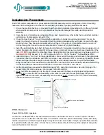
7. Hook the PWS sub-assembly on to the top of the wall plate with the face panel light pipes facing upward.
Gently push to lower the PWS sub-assembly until contact is made with the wall plate. Apply firm pressure
against the bottom of the PWS sub-assembly until an audible “snap” is heard or felt. The PWS sub-assembly
should now be flush to the wall.
PWS Removal
Power OFF the PWS if possible.
To remove an installed PWS, a flat head screwdriver with a slot width of 3/16” to ¼” will be required. Insert the
screwdriver into one of the two extraction holes on the bottom of the face panel sub-assembly. Gently and slowly
twist the screwdriver until the face panel “pops” away from the wall mount plate. It may be possible that procedure
is required for both extraction holes. Unhook the top of the subassembly from the top of the wall plate and gently
remove the station from the wall.
Hook PWS onto Wallplate at an angle.
Push down onto Wallplate.
Snap PWS onto Wallplate.
Wall
Electrical
Back Box

