background image

WWW.JOHNSONSYSTEMS.COM

29

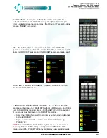
PRESET PLAYBACK
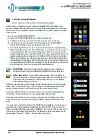
Navigate to the desired preset and tap the preset. Positive preset activation 

will be indicated visually by the preset becoming a solid color and audibly 

if the audio feature has been selected and set. The gray bar at the top of 

the display will fade across matching the FADE TIME programmed and the 

PRESET output level will display the real-time DMX fading from 0-100%. 

The last fade preset with dimmers assigned will display to the left of the 

fade in progress bar.
SPECIAL CASE - PRESET EDIT SCREEN
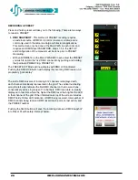
Upon exit of the PRESET EDIT menu:
ADMIN

•  If the ADMIN has changed any of the settings, the ADMIN will be 

allowed to save the changes.

•  Re-entry of the PRESET EDIT screen will not require re-entry of the 

password.

USER
A USER will only be allowed access to the LEVELS screen and the 

Master Slider. The Master Slider will permit adjustment of all live channels 

programmed into the active Preset ± 50% from the previously recorded 

level.
Upon exit of the PRESET edit menu:

•  If the USER has made any changes to the settings, no prompt to 

SAVE changes will be displayed. The new settings will be active for 

the current PRESET but not saved.

•  Re-entry of the Preset edit screen will require re-entry of the 

password.

FIRMWARE UPGRADES

•  PWS ship with an imbedded Bootloader that allows for field upgrades with a standard PC laptop and 

USB cable. This application and new firmware will be available at no charge for bug fixes and or product 

deficiencies on demand for the 2 year warranty period of the PWS. Enhanced system capabilities 

and features may require a small fee to offset development cost. Please inquire via email to info@

johnsonsystems.com

Содержание Presidor Wall Station

Страница 1: ...S E Calgary Alberta Canada T2G 5M1 tel 403 287 8003 fax 403 287 9003 e mail info johnsonsystems com website www johnsonsystems com Wall Station PWS Installation Guide and User Manual JOHNSON SYSTEMS INC WWW JOHNSONSYSTEMS COM ...

Страница 2: ...act our factory via email info johnsonsystems com or phone 403 287 8003 during business hours Monday to Friday 8 00AM to 5 00PM MST Contents Characteristics 4 Drawings Details 4 Description of Operation 6 Installation 6 Model PWS 70P DMX 7 Model PWS 20P RETRO 10 Installation Procedure 13 PWS Removal 13 Replacement Plastic Kits 14 Presidor Adaptor Plates 14 Presidor Surface Boxes 14 Initial Set Up ...

Страница 3: ... LED fixtures churches corporate boardrooms hotel ballrooms convention facilities museums art galleries and other DMX512 or RS232 controlled devices Features Attractive Patent Pending screwless design is ergonomic and sealed to dust 70 presets on one universe of DMX512 channels Operates as either a DMX console or a DMX snapshot playback device State of the art high speed low power green processor ...

Страница 4: ...eration and 1 4 Watt during standby mode Cabling Model PWS 70P DMX RS485 Cat5 5e 6 cable RJ 45 or retrofit into existing Belden 9773 or equivalent terminal block 300m max 1000 Model PWS 20P RETRO 4 x 22 AWG or larger wires Typical 1000 or 300m on 18 AWG wiring Operating Conditions 0 C to 40 C 32 F to 105 F 10 90 relative humidity non condensing Drawings Details Models PWS 70P DMX PWS 20P RETRO ...

Страница 5: ...WWW JOHNSONSYSTEMS COM 5 Drawings Details Model Room Linker Combiner PRLC 4 Model PRLCR 4U PRLC 19 Wall Rack 4 rack units Supports up to 4 x PRLC 4 Hinged Front Rear Wall Tub ...

Страница 6: ...one wiring in a daisy chain topology There must be a Main Station in each wiring LAN Local Area Network with one Main PWS per room zone Each LAN and Main PWS may have up to 14 Secondary PWS s connected to it The Main PWS will output DMX data for the room directly to the DMX receiving device or to a DMX input of a Presidor Room Linker Combiner PRLC 4 in a multi room application Installation There a...

Страница 7: ...unication between multiple PWS will be PMX multiplex RS485 protocol Model PWS 70P DMX Configuration and DIP Switch Settings Important One station in each LAN must be designated as a Main PWS switch 4 ON Only one Main Station per LAN All Secondary PWS connected to the Main PWS maximum 14 PWS must have switch 4 turned OFF Important Communication between Main PWS and Secondary PWS is PMX protocol Pre...

Страница 8: ...SWITCH 2 ON FOR 1st LAST ROOM STATIONS DIP SWITCH 2 ON FOR 1st LAST ROOM STATIONS Typical PWS 70P DMX Wiring and Connection Detail Typical PWS 70P DMX Single Room Wiring Topology 1 Typical PWS 70P DMX Single Room Wiring Topology 2 ...

Страница 9: ...m Console or DMX Source AUX Sensor Contact Cat 5 5e 6 Patch Cable Cat 5 5e 6 Patch Cable Cat 5 5e 6 Patch Cable Cat 5 5e 6 Patch Cable To Secondary PWS 3 14 Typical PWS 70P DMX Multi room Wiring Topology PWS 70P DMX Cat 5 5e 6 Interconnect PRLC Room Linker Combiner ...

Страница 10: ...ontrol upgrades to facilities that would otherwise be faced with a very expensive wiring replacement cost Minimum of 4 wires required Maximum distance dependent on wire type and gauge Typical 1000 or 300m on 18 AWG wiring Model PWS 20P RETRO Configuration and DIP Switch Settings Important One station in each wiring LAN must be designated as a Main PWS switch 4 ON Only one Main Station per LAN All ...

Страница 11: ...WWW JOHNSONSYSTEMS COM 11 Typical PWS 20P RETRO Wiring and Connection Detail Typical PWS 20P RETRO Single Room Wiring Topology 1 Typical PWS 20P RETRO Single Room Wiring Topology 2 ...

Страница 12: ...2 SECONDARY 1 MAIN DMX IN from Console or DMX Source AUX Sensor Contact Optional Cat 5 5e 6 Patch Cable To Secondary PWS 3 14 PWS 20P RETRO Multi Room Interconnect PRLC Room Linker Combiner Typical PWS 20P RETRO Multi Room Wiring Topology ...

Страница 13: ...5 Label all wiring as to or from for future identification Dress out all the wiring and terminate to the appropriate connectors based on installation and PWS model type Leave at least an 8 12 service loop if possible Ensure all wire is stripped back far enough to ensure full plug insertion without insulation Plug all the terminated wiring connectors to their final location on the PWS I O PCB Tape ...

Страница 14: ...ng to 1 gang Adaptor Plate White PA 4A1 Black 4 gang to 1 gang Adaptor Plate Black PA 4A1 Black 4 gang to 1 gang Adaptor Plate Black PA 5A1 White 5 gang to 1 gang Adapter Plate White PA 5A1 Black 5 gang to 1 gang Adapter Plate Black PA 6A1 White 6 gang to 1 gang Adapter Plate White PA 6A1 Black 6 gang to 1 gang Adapter Plate Black PA 7A1 White 7 gang to 1 gang Adapter Plate White PA 7A1 Black 7 ga...

Страница 15: ... minutes of inactivity on the station will automatically initiate the SLEEP MODE Two levels of illumination are programmable for this setting The station will automatically exit this mode and wake up to PRESET MODE if the display is touched or if any motion is detected by the proximity sensor within the range it is programmed for maximum 3 meters or 10 feet 2 PRESETS Normal Run mode for any PWS Al...

Страница 16: ...pped from the factory fully masked with no channels selected Each channel can be assigned as a dimmer DIM non dim ND or task light TASK 3 PRESET ENABLE DISABLE PWS are shipped defaulted with the first 10 presets enabled Up to 70 presets are available in 7 different colors Enable the desired number of presets 4 DATE TIME Set the date and time in various display formats 5 SYNC AND LOCK Synchronize a...

Страница 17: ...assword is stored in the removable external EEPROM plug in module on the rear of the PWS Passwords are entered at the room Main PWS only and then shared with the room Secondary PWS via the SYNC command Important On SYNC Main Secondary all Secondary PWS will have the same password as the room zone Main PWS The user will not be able to change the password on a Secondary either manually or with the D...

Страница 18: ...somewhere for future reference b If the user forgets their password setting DIPSW 3 ON will allow the user to enter a new password This procedure will involve the temporary removal of the Main PWS from the wall please see page 13 This must be done carefully with the power remaining ON PWS Rear Panel View When DIPSW 3 is on 4 Red bars are shown on the password screen and the n key is now active Ent...

Страница 19: ...equire a PASSWORD to access will show a small red lock symbol at the top left side of the screen see right Once unlocked with a valid PASSWORD entry the screen will allow access to additional functions on the screen see the tool wrench that now appears below This allows additional set menus for an ADMIN level person and is covered in more detail further in this manual Important Security timeout Af...

Страница 20: ...S stations room within a room operation TASK assignment to a specific DMX channel or group of channels permits toggle Non Dim control between 0 and 100 DMX control output with a trigger point of approximately 3 DMX Room with a room operation is limited to presets 61 70 Task lights assigned in presets 1 60 will operate as Non Dims only on preset execution Example TASK circuit assignment Several gri...

Страница 21: ...o operate on the same wiring LAN Each Main PWS may have independent Secondary PWS connected to it Maximum 15 PWS per LAN The output of the upstream Main PWS must be hardwired to the input of the downstream Main PWS Important External DMX sources can NOT be used to record snapshots for Presets in this mode DMX SET CLEAR Quick set up buttons are also provided for fast default programming in the abov...

Страница 22: ... or fewer presets at a PWS will increase the physical pad size of the preset and increase the contact surface area of preset activation 4 DATE TIME Set the date and time and permit choice of display in various formats USER and ADMIN PASSWORD access permitted 5 SYNC AND LOCK Synchronize all Secondary PWS connected to the room Main PWS Relevant data will be shared from the Main to the Secondary PWS ...

Страница 23: ...n feature for museums and art galleries The preset numbers can be changed 7 SCHEDULE Permits selection of up to 70 presets for automatic activation via the onboard Real Time Clock RTC One minute increments 24 7 365 SCHEDULE SELECT Scroll up down to select the SCHEDULE which you would like to assign and push a SCHEDULE EDIT SCHEDULE Selecting a SCHEDULE will pull up the EDIT SCHEDULE screen SCHEDUL...

Страница 24: ...HEDULE PRESET NUMBER Select the PRESET you wish to activate at the previously selected time and days Press the back arrow to return to EDIT SCHEDULE REPEAT ONCE Select frequency of automatic PRESET activation from the RTC ENABLE DISABLE Turn the SCHEDULE ON or OFF for different seasons and lighting demands 8 AUDIO Selection of audio type and volume ...

Страница 25: ...cally wake up from its Low Power Energy Saving SLEEP MODE when it detects a user within range of it Maximum Infrared detection distance approx 6 or 1 5m 10 BACKLIGHT Sensitivity selection of the ambient light sensor for desired level of station illumination during operation SLEEP MODE illumination select 11 BLUETOOTH FUTURE Coming for 2021 ...

Страница 26: ...T 01 The PRESET EDIT Mode will now display with DMX LIVE indicated Pushing the DMX LIVE button with display the incoming DMX levels on a proprietary grid display The entire DMX universe of incoming 512 channels is displayed with each channel individually represented in the grid The vertical numbering along the left side indicates the first DMX channel on that row and runs consecutively across in g...

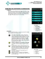
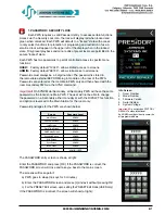
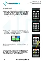
Страница 27: ...allow each PRESET to have a customizes fade time Maximum FADE TIME is 1 hour 2 PROGRAM A PRESET FROM THE PWS This method of PRESET recoding can be done at any MAIN PWS without a DMX source An ADMIN level PASSWORD is required Steps 1 5 in the SET UP and Configuration of the manual must be done prior to PRESET Recording Select the PRESET you wish to program by pushing and holding that particular PRE...

Страница 28: ...ch slider Non Dim channels will be displayed as ON OFF symbols where ON is Green and OFF is Red Grey when disabled Push to toggle TASK Lights will be displayed as ON OFF symbols where ON is Light Blue and OFF is Dark Blue Grey when disabled Push to toggle More examples below In the examples above 1 The PRESET number 22 0f 70 possible is displayed at the top left 2 Navigation across the PRESET is p...

Страница 29: ...of the password USER A USER will only be allowed access to the LEVELS screen and the Master Slider The Master Slider will permit adjustment of all live channels programmed into the active Preset 50 from the previously recorded level Upon exit of the PRESET edit menu If the USER has made any changes to the settings no prompt to SAVE changes will be displayed The new settings will be active for the ...

Страница 30: ...23 Highfield Crescent S E Calgary Alberta Canada T2G 5M1 tel 403 287 8003 fax 403 287 9003 e mail info johnsonsystems com website www johnsonsystems com WWW JOHNSONSYSTEMS COM User Manual Rev 1 March 2021 ...

Отзывы: