ZFR1812 Wall Mount Wireless Field Bus Router Installation Instructions
4
6.
Tighten the security screw to prevent tampering
using a 1.5 mm (1/16 in.) Allen wrench or a
Johnson Controls® T-4000-119 Allen-Head
Adjustment Tool. Use caution when tightening the
screw to avoid stripping the plastic threads in the
ZFR1812.
Mounting in a Wall Plate - ZFRRPTK-H2
Note:
The wall plate is intended to attach to a
mudplate rather than directly to the wall.
1.
Separate the plastic base and circuit board
assembly (cover). Do not remove the security
screw from the cover. See Figure 2.
IMPORTANT:
The label showing the unit MAC
address is on the plastic base of the unit. Be sure to
keep the plastic base and circuit board assemblies
together so the correct MAC address is shown.
2.
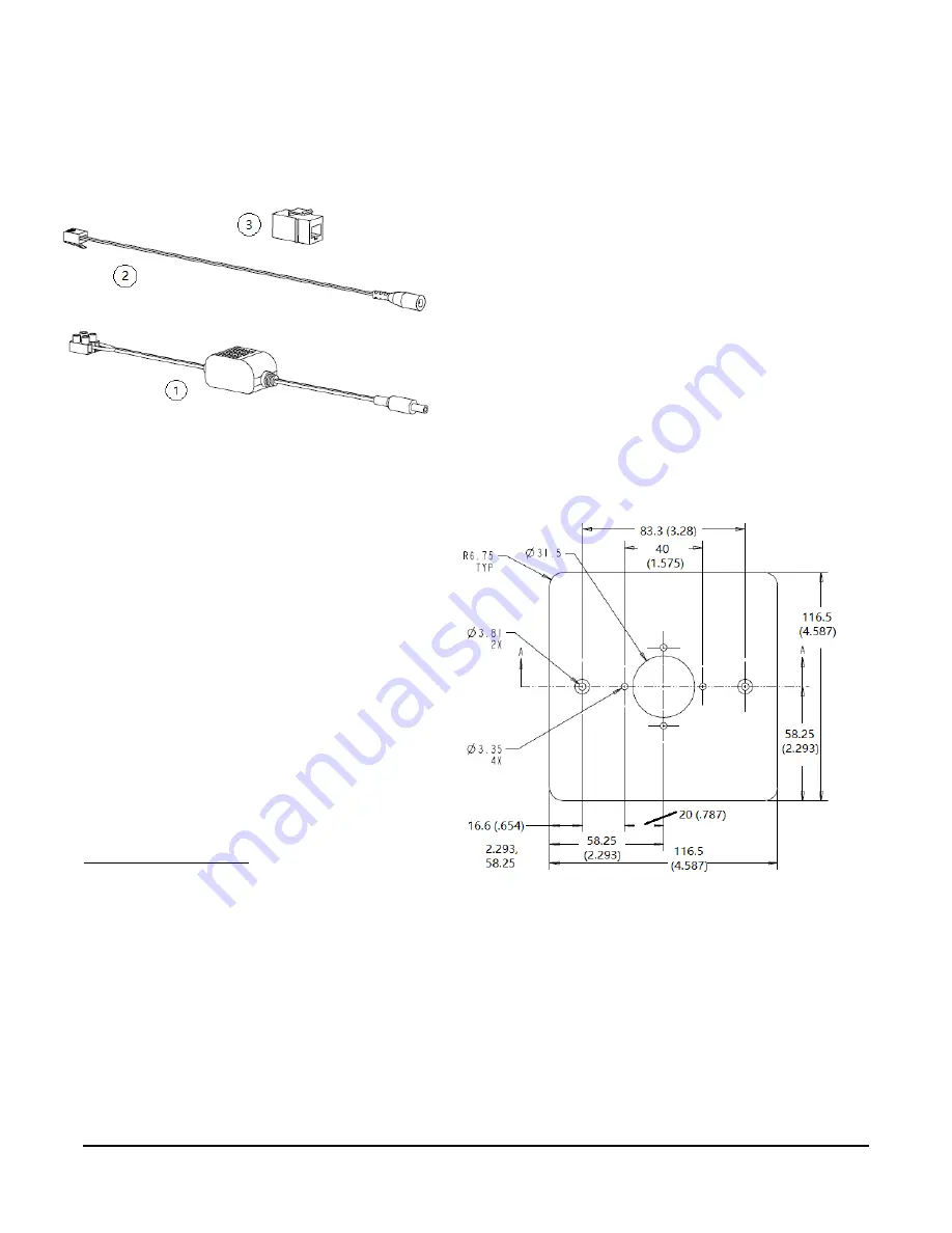
Attach the plastic base to the supplied wall plate.
Figure 5 shows the wall plate dimensions.
3.
Connect the external cable assembly to the 6-pin
modular receptacle.
4.
Set the DIP switches. (See
5.
Reattach the circuit board assembly in the plastic
base.
6.
Tighten the security screw to prevent tampering
using a 1.5 mm (1/16 in.) Allen wrench or a
Johnson Controls® T-4000-119 Allen-Head
Adjustment Tool. Use caution when tightening the
screw to avoid stripping the plastic threads in the
ZFR1812.
7.
Assemble the external power and adapters as
necessary (Figure 4). Note that the power supply
can be secured in an electrical box with the
provided two-sided tape. An electrical box is not
included with the kit.
a.
The 24 VAC to 15 VDC power supply (1) uses
screw terminals to attach to a 24 volt source.
b.
The adapter connects the 15 VDC output of the
power supply to an RJ12 adapter (2). This
adapter can be plugged directly into the RJ12
jack on the ZFR1812 or connected to a
connector (3).
c.
This connector (3) is then used to connect to
the 10ft RJ12 cable which is attached to the
ZFR1812.
8.
Mount the wall plate with ZFR1812 in the selected
location using standard box screws. Be sure to
leave enough slack in the cable so you can still pull
the ZFR1812 if you need to change the DIP
switches.
Figure 4: Power supply and adapters
Figure 5: ZFR1812 Wireless Field Bus Router,
Wall Plate Dimensions mm (in.)


