background image

JOHNSON CONTROLS

16

FORM 160.00-O10 

ISSUE DATE: 8/24/2020

SECTION 2 - SAFETY SHUTDOWNS
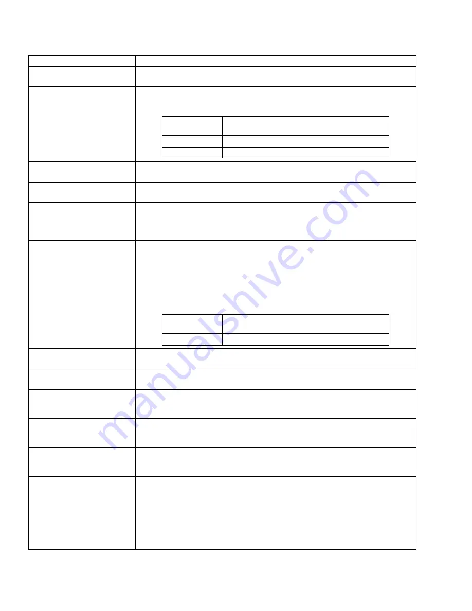
MESSAGE

DESCRIPTION

VSD – HIGH PHASE C INPUT 

BASEPLATE TEMPERATURE

See “VSD – HIGH PHASE A INPUT BASEPLATE TEMPERATURE” message preceding.

VSD – HIGH PHASE A MOTOR 

BASEPLATE TEMPERATURE

The chiller has shutdown because the motor baseplate temperature exceeded the 

shutdown value for the given model of drive listed below. After the unit trips, the VSD 

fan(s) and water pump(s) shall remain energized for 2 minutes after the fault occurred. 

DRIVE MODEL

HIGH PHASE A MOTOR BASEPLATE 

TEMPERATURE SHUTDOWN VALUE

1100

160°F (71.1°C)

1300

150°F (65.5°C)

VSD – HIGH PHASE B MOTOR 

BASEPLATE TEMPERATURE

See “VSD – HIGH PHASE A MOTOR BASEPLATE TEMPERATURE” message 

preceding.

VSD – HIGH PHASE C MOTOR 

BASEPLATE TEMPERATURE

See “VSD – HIGH PHASE A MOTOR BASEPLATE TEMPERATURE” message 

preceding.

VSD – HIGH TOTAL DEMAND 

DISTORTION

This shutdown indicates the input current to the VSD is not sinusoidal. This shutdown will 

occur if the Total Demand Distortion (TDD) exceeds 25% continuously for 45 seconds. 

The displayed TDD is the sum of the harmonic currents up to the 50th harmonic supplied 

by the main power to the VSD divided by the Full Load Amps. 

VSD – INPUT CURRENT 

OVERLOAD

The input current overload value is variable based on the Input Job Full Load Amps value 

programmed at the Control Panel. The input current overload value is 1.16 times the 

Input Job Full Load Amps value, but not to exceed the value for the given model of drive 

listed below. This calculation takes into account installations where the input line voltage 

could be up to 10% below the nominal value. An additional 5% of current is added to 

reduce nuisance shutdowns due to power fluctuations. To provide addition time for the 

chiller too unload, the input current overload value must be greater than the shutdown 

value for 10 continuous seconds for this shutdown to occur.

DRIVE MODEL

INPUT CURRENT OVERLOAD MAXIMUM 

SHUTDOWN VALUE

1100/1300

1305 Amps

VSD – INPUT DCCT OFFSET 

LOCKOUT

If three consecutive VSD – Phase A, B or C Input DCCT Offset cycling faults occur, this 

safety shutdown is generated to require investigation and manual reset.

VSD – INVERTER PROGRAM 

FAULT

The VSD software contains a verification process to ensure that the correct set of 

software is installed in the VSD logic board for the application.

VSD – LINE VOLTAGE PHASE 

ROTATION

The input voltage to the VSD is not phase rotation sensitive, but the VSD must be able to 

determine the correct input phase rotation. If the VSD logic board cannot determine the 

correct phase rotation, then this shutdown is generated.

VSD – LOGIC BOARD 

HARDWARE

After power is applied to the chiller, the VSD logic board performs several internal tests to 

ensure proper operation of the input power device. If the tests fail, then this shutdown is 

generated. 

VSD – LOGIC BOARD PLUG

A jumper is located in the rectifier and inverter current transformers connectors that 

indicate the connector is properly installed. If either connector is not installed, then this 

shutdown is generated.

VSD – MOTOR CURRENT 

IMBALANCE

Each phase of motor current is compared against the average of the three phases of 

motor current to determine the current imbalance value. If the current imbalance value is 

greater than 32 amps for a period of 45 seconds, then this shutdown is generated. For 

example: The three motor current RMS values are 200, 225, and 240 amps. This would 

calculated to an average current of (200 + 260 + 240)/3 = 233 amps. Subtract the real 

current value from the average value. 200 – 233 = 33, 260 – 233 = 33, 240 – 233 = 7. If 

this condition or worse were maintained for 45 seconds, then this shutdown is generated, 

because the motor current imbalance is 33 amps. 

TABLE 2 -

 SAFETY SHUTDOWNS MESSAGE (CONT'D)

Содержание YORK HYP1100A

Страница 1: ...415 VAC 371 06172 XXX 1300 HP 60 HZ 460 VAC 371 06172 XXX MODELS HYP1100A HYP1300A LIQUID COOLED OPTISPEED COMPRESSOR SPEED DRIVE OPERATION MANUAL Supersedes 160 00 O10 217 Form 160 00 O10 820 Issue...

Страница 2: ...this document and any referenced materials This in dividual shall also be familiar with and comply with all applicable industry and governmental standards and regulations pertaining to the task in que...

Страница 3: ...g and operating service personnel should verify whether the equipment has been modified and if current literature is available from the owner of the equipment prior to performing any work on the chill...

Страница 4: ...173 Retrofit Package YK Filter Model HYP1100RKC30B 50A 371 06172 175 Retrofit Package YK Filter Model 1100 HP 400 VAC HYP1100RKC30B 42A 371 06172 185 Retrofit Package YK Filter Model HYP1100RKC30B 50...

Страница 5: ...Demand Distortion 16 VSD Input Current Overload 16 VSD Input DCCT Offset Lockout 16 VSD Inverter Program Fault 16 VSD Line Voltage Phase Rotation 16 VSD Logic Board Hardware 16 VSD Logic Board Plug 1...

Страница 6: ...B Input Gate Driver 21 VSD Phase C Input Gate Driver 21 VSD Phase A Motor Gate Driver 21 VSD Phase B Motor Gate Driver 21 VSD Phase C Motor Gate Driver 21 VSD Precharge Low DC Bus Voltage 1 21 VSD Pre...

Страница 7: ...power devices required for one phase of input and output In other words the rectifier and inverter are integrated into one power unit This design has 2 methods of detecting a ground fault The circuit...

Страница 8: ...COMPRESSOR DRIVE DETAILS The 1300 HP drive contains 3 power assemblies Each power assembly contains 2 capacitors with the rectifier of the left side of the power assembly and the inverter on the righ...

Страница 9: ...OSCD to provide input current limit ground fault detection and information for the harmonic current filtering The bus voltage is moni tored to verify that bus voltage is present The line volt age is...

Страница 10: ...SSUE DATE 8 24 2020 SECTION 1 GENERAL INFORMATION Figure 1 HYP1100A HYP1300A HP COMPLETE DRIVE CABINET Cooling Coil Supply Contactor Fan Assembly A Phase Power Assembly B Phase Power Assembly BUS Stru...

Страница 11: ...RMATION FORM 160 00 O10 ISSUE DATE 8 24 2020 1 Figure 2 LEFT SIDE OF HYP1100A HYP1300A HP DRIVE CABINET Voltage Transient Board Line Voltage Isolation Board Drive Logic Board Cooling Fans Cooling Coil...

Страница 12: ...JOHNSON CONTROLS 12 FORM 160 00 O10 ISSUE DATE 8 24 2020 SECTION 1 GENERAL INFORMATION Figure 3 RIGHT SIDE OF HYP1100A HYP1300A HP DRIVE CABINET Inlet Coolant Hose Step Down Transformers LD21854...

Страница 13: ...JOHNSON CONTROLS 13 SECTION 1 GENERAL INFORMATION FORM 160 00 O10 ISSUE DATE 8 24 2020 1 Figure 4 DRIVE LOGIC BOARD LD16293 Figure 5 RECTIFIER SIDE OF THE POWER UNIT HYP1100A AND HYP1300A LD16292...

Страница 14: ...ogether through a ModBus communication link Data such as output currents baseplate temperatures and input voltage are communicated from the OSCD to the microboard for display through the ModBus commun...

Страница 15: ...pre charge to start The unit s fan s and water pump s shall remain energized during this wait time The VSD shall allow up to three consecutive pre regulation related faults i e VSD DC BUS PRE REGULAT...

Страница 16: ...he input current overload value must be greater than the shutdown value for 10 continuous seconds for this shutdown to occur DRIVE MODEL INPUT CURRENT OVERLOAD MAXIMUM SHUTDOWN VALUE 1100 1300 1305 Am...

Страница 17: ...unt of current is flowing to the motor If at the end of the 1 5 second time a minimum of 25 amps peak is not detected then this shutdown is generated VSD PHASE B MOTOR DCCT See VSD PHASE A MOTOR DCCT...

Страница 18: ...JOHNSON CONTROLS 18 FORM 160 00 O10 ISSUE DATE 8 24 2020 THIS PAGE INTENTIONALLY LEFT BLANK...

Страница 19: ...ltage exceeds the value for the given model of drive then this shutdown will occur Typically this shutdown will occur when there is a sudden change in the input voltage due to storms utility power pro...

Страница 20: ...this fault There are several causes for an unsuccessful initialization as follows Serial data communications must be established Refer to VSD Serial Communications fault If communications between the...

Страница 21: ...message preceding VSD PHASE A INPUT GATE DRIVER The gate driver board for the input rectifier monitors the power supplies within the gate driver circuit and verifies that the input rectifier can be p...

Страница 22: ...IVE This shutdown is generated when the VSD logic board has not received a valid communications packet from the control center for 10 consecutive seconds VSD SHUTDOWN REQUESTING FAULT DATA The VSD has...

Страница 23: ...tice we have no objections as long as the OSCD is properly grounded Can I apply an OptiSpeed Compressor Drive to a generator Yes the OSCD can be applied to a generator No modi fications are required f...

Страница 24: ...ennsylvania USA 17349 1 800 524 1330 Subject to change without notice Printed in USA Copyright by Johnson Controls 2020 www johnsoncontrols com ALL RIGHTS RESERVED Form 160 00 O10 820 Issue Date Augus...

Отзывы: