TEC2102-3 N2 Networked Heat Pump Thermostat Installation Instructions
8
You must not have a Relinquish Default for the
setpoints if you want to change them from the
thermostat display.
If there is a Relinquish Default for the setpoints, the
Network Automation Engine (NAE) always has an
Override for either an adjusted value or the Relinquish
Default Value. You should use Operator Override and
Release Operator Override if you want to command the
setpoint and release it to local control.
Once all the NAE commands are released, the
Override Status in the Hardware tab should be False.
At that time, the user should be able to change the
setpoint from the local display.
All overrides are released automatically after 10
minutes of no communications (for example, network
cable is removed from the TEC, causing loss of
network communications).
Setup and Adjustments
Thermostat Operation Overview
Thermostat User Interface Keys
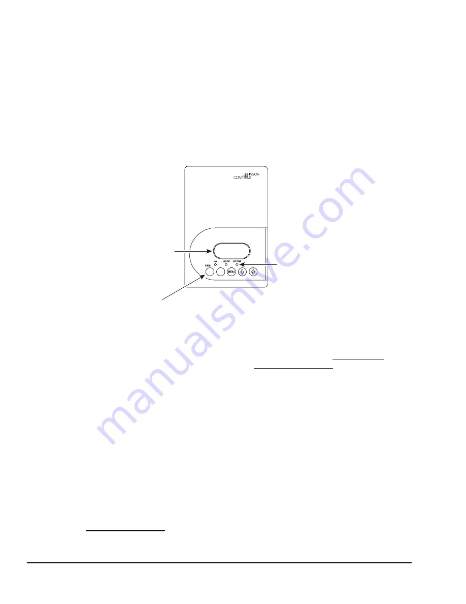
The TEC2102-3 Thermostat user interface consists of
five keys on the front cover (as illustrated in Figure 7).
The function of each key is as follows:
•
Use the
YES/SCROLL
key to:
-
confirm menu selections and to advance to the
next menu item
-
stop the Status Display Menu from scrolling
and to manually scroll to the next parameter on
the menu
Note:
When the thermostat is left unattended for
45 seconds, the thermostat display resumes scrolling.
•
Use the
NO
key to decline a parameter change and
to advance to the next menu item.
•
Use the
MENU
key to:
-
access the Main User Menu or to exit the menu
(See the
Programming Overview
section.)
-
access the Installer Configuration Menu or to
exit the menu (See the
Configuring the
TEC2102-3 Thermostat
section.)
•
Use the
UP/DOWN
arrow keys to change the
configuration parameters and to activate a setpoint
adjustment.
Backlit Liquid Crystal Display (LCD)
The TEC2102-3 Thermostat includes a 2-line,
8-character backlit display. Low-level backlighting is
present during normal operation, and it brightens when
any user interface key is pressed. The backlight returns
to low level when the thermostat is left unattended for
45 seconds.
Light-Emitting Diodes (LEDs)
Three LEDs are included to indicate the fan status, call
for heat, or call for cooling:
•
The
FAN
LED is on when the fan is on.
•
The
AUX HEAT
LED is on when auxiliary heat is
on.
Figure 7: Front Cover of Thermostat
70.0ºF
Room Temp
YES
NO
Backlit, plain text
LCD is easy to read
in any condition.
Five keys on the thermostat
make operation easy and intuitive.
LEDs indicate
system activity.
F
IG
:f
rn
t_
v
w


