TEC2001-4 and TEC2001-4+PIR Single-Stage Wireless Thermostat Controllers Installation Instructions
5
Setup and Adjustments
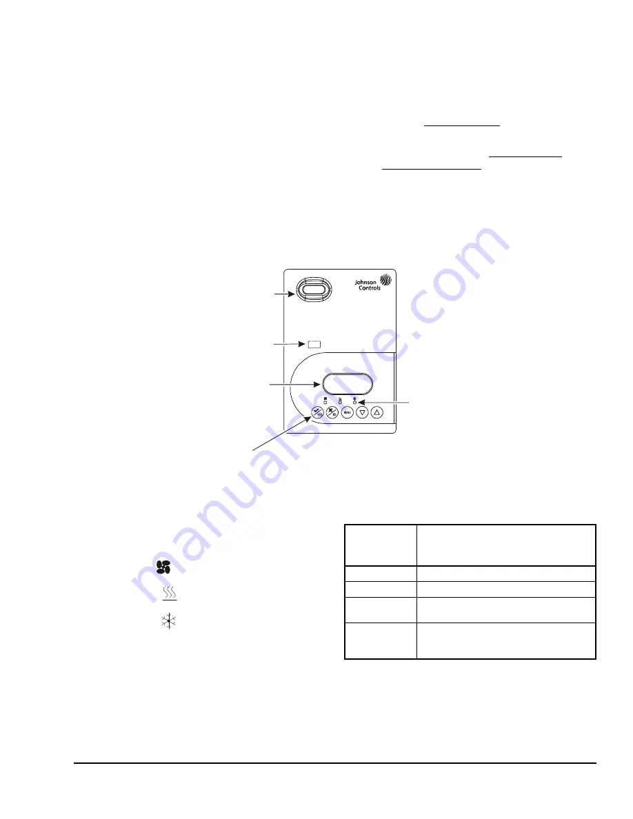
Thermostat Controller User Interface Keys
The user interface consists of keys on the front cover
(Figure 6). The function of each key is as follows:
•
Use the
YES
key to:
-
confirm menu selections and to advance to the
next menu item
-
stop the Status Display Menu from scrolling
and to manually scroll to the next parameter on
the menu
Note:
When the thermostat controller is left
unattended for 45 seconds, the display resumes
scrolling.
•
Use the
NO
key to decline a parameter change and
to advance to the next menu item.
•
Use the
MENU
key to:
-
access the Main User Menu or to exit the menu
(See the
Main User Menu
section.)
-
access the Installer Configuration Menu or to
exit the menu (See the
Configuring the
Thermostat Controller
section.)
•
Use the
UP/DOWN
arrow keys to change the
configuration parameters and activate a setpoint
adjustment.
Light-Emitting Diodes (LEDs)
Three LEDs are included to indicate the fan status, call
for heat, or call for cooling:
•
The fan LED
is on when the fan is on.
•
The heat LED
is on when heating is on.
•
The cool LED
is on when cooling is on.
The Status LED, located beneath the cover, flashes at
5-second intervals to provide indication of the network
Figure 6: Front Cover of Thermostat Controller (TEC2001-4+PIR Model Shown)
70.0ºF
Room Temp
Backlit, plain text
Liquid Crystal Display (LCD)
is easy to read in any condition.
Five keys on the thermostat controller
make operation easy and intuitive.
Light-Emitting Diodes (LEDs)
indicate system activity.
FIG
:20
01-
4f
rn
t_
vw
PIR motion detector
saves energy using
standby setpoints.
Status LED beneath cover
indicates network status.
Table 2: Status LED
Flashes per
5-Second
Interval
Condition Indicated
1
Power On
2
Power On, Communicating
3
Power On, Communicating, Found
Wireless Network
4
Power On, Communicating, Found
Wireless Network, Communicating with
TEC20 Coordinator


