JOHNSON CONTROLS
7
FORM 130.13-NOM8 (1021)
Hanger straps may be utilized as an alternate means
of suspending the equipment. Do not secure hanger
straps to electric heater ducts, coils, or control
enclosures. Hanger straps can be mounted directly to
the sides and bottom of equipment casing, such that
they do not interfere with working components or access
panels. Before securing screws, ensure they will not
damage internal components. Screw length should be
limited to 5/8”.
When hanging equipment, always use the support
method as prescribed for rectangular duct in the job
specifications. If unit is to be flipped in the field, refer
to 180-degree unit flip and access door reassignment
instructions on page 11.
Duct Connections
All duct connections should be configured and installed
in accordance with SMACNA guidelines and all local
code requirements. Check to see that duct fasteners
are appropriate for the application and do not impinge
any internal components. Pay particular attention to
internal electrical components.
Fasten and seal all ductwork connections in accordance
with project specifications. Allow a minimum of 1½ duct
diameters of straight duct prior to equipment inlet.
The diameter of the inlet duct for round valves must be
equal to the listed size of the equipment. The round
air valve inlet collar of the equipment is 1/8” smaller
then listed size in order to allow the round ductwork
to slip over the air valve inlet collar.
DO NOT INSERT
DUCTWORK INTO AIR VALVE INLET COLLAR.
When making ductwork connection to air valve inlet
collar and insulating air valve inlet, take caution not to
damage or remove the flow sensor connections, which
are vital to equipment control.
Provide insulation around entire inlet collar (all the way
to the equipment casing).
Cut “slits” in the insulation for the flow tubes and secure
with duct tape.
Permissible discharge duct connections are straight
flanged, slip and drive or drive and screw.
After all connections are made, check that the entire
ductwork system is airtight. In some high-pressure
systems, duct sealer may be necessary.
Sound Critical Applications
Flexible duct connectors are not recommended on
equipment discharge. The sagging membrane of
these fittings can cause turbulence and locally high
air velocities that generate noise. Also, lightweight
membrane material allows noise to break out, which
can increase sound levels in the space below.
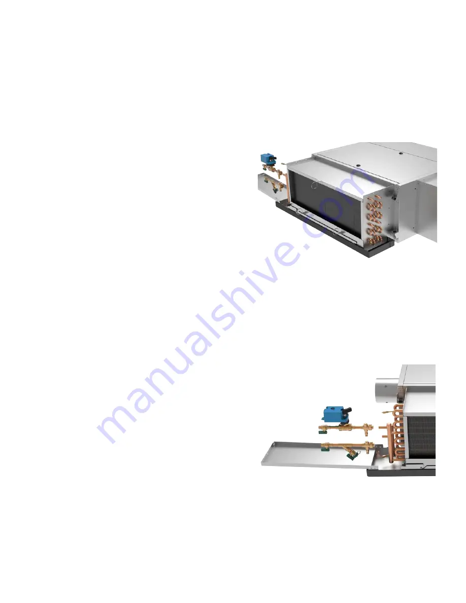
Drip Pan and Auxiliary Drip Pan
Standard drip pans are externally insulated, single
wall galvanized steel. The drip pan is easily removable
for cleaning. The optional auxiliary drip pan to catch
condensed moisture from valves and piping is easily
attachable to the drip pan. Care must be taken to ensure
that the unit drip pan does not slope away from the
outlet connection.
Auxiliary Drip Pan
The auxiliary drip pan ships attached to the top of the
coil casing, and mounts directly to the unit drip pan using
(4) field-provided #10 x 1/2” screws.
After the connections are completed, the system should
then be tested for leaks. Since some components are
not designed to hold pressure with a gas, hydronic
systems should be tested with water.


