background image

JOHNSON CONTROLS

9

FORM 130.13-NOM8 (1021)

Cooling/Heating Medium Connections

Coils  are  male  sweat  connection.    Use  appropriate 

brazing  alloy  for  system  temperature  and  pressure.  

Refer to equipment construction submittal drawing for 

specific connection size.  

MAXIMUM HYDRONIC COIL 

OPERATING PRESSURE MUST NOT EXCEED 450 
PSIG.

In the event that leaking or defective components are 

discovered, the Sales Representative must be notified 

BEFORE any repairs are attempted. All leaks should be 

repaired before proceeding with the installation.

Valves must be secured and supported to avoid damage 

to coil headers. All valves, pipes, and components must 

be sufficiently supported to ensure structural integrity 

and proper operation of the unit.

After system integrity has been established the piping 

should be insulated in accordance with the project 

specifications. ALL chilled water and drip pan piping 

not located over drip pans must be insulated to prevent 

damage from sweating. This includes factory and field 

piping inside the unit cabinet.

The drain should always be connected and piped to an 

acceptable disposal point. For proper moisture carry-off, 

the drain piping should be sloped away from the unit 

at least 1/8” per foot. A drain trap may be required by 

local codes and it is strongly recommended for odor 

containment.

If necessary, you can change hot water coil connection 
handing on one and two row coils from left-hand to right-
hand (and vice-versa) by rotating the coil “like a steering 

wheel” 180° about its central axis when facing the fins. 

NOTE: When the coil is flipped, the vent will no longer 

perform in a vent capacity. It is suggested that valve 

packages are re-oriented during this process to bring 

the valve actuator back to its original position.

Piping Connections

Toxic  residues  and  loose  particles 

resulting  from  manufacturing  and 

field piping techniques such as joint 

compounds, soldering flux, and metal 

shavings may be present in the unit 

and the piping system. Special con

-

sideration  must  be  given  to  system 

cleanliness when connecting to solar, 

domestic or potable water systems.

Submittals  and  Product  Catalogs  detailing  unit 

operation, controls, and connections should be 

thoroughly reviewed BEFORE beginning the connection 

of the various cooling and/or heating mediums to the 

unit All accessory valve packages should be installed 

as required, and all valves should be checked for proper 

operation.

If coil and valve package connections are to be made 
with “sweat” or solder joint, care should be taken to 
assure that no components in the valve package are 
subjected to a high temperature which may damage 

seals  or  other  materials.  Many  two-position  electric 

control valves, depending on valve operation, are 

provided with a manual-opening lever. This lever should 

be placed in the “open” position during all soldering or 

brazing operations.  Valve bodies should be wrapped 

with a wet rag to help dissipate heat encountered during 

brazing.  Use a brazing alloy to make connections. Soft 

solder is not recommended. 

If the valve package connection at the coil is made with 
a union, the coil side of the union must be prevented 
from twisting (“backed up”) during tightening to prevent 

damage  to  the  coil  tubing.  Over-tightening  must  be 

avoided to prevent distorting the union seal surface 

and destroying the union.  In the case of field installed 

valves and piping, the chilled water valve cluster should 
be installed in such a way that any dripping or sweating 

is contained in the auxiliary drip pan or other device.  

Valves should be secured or supported to avoid damage 

to coil headers.

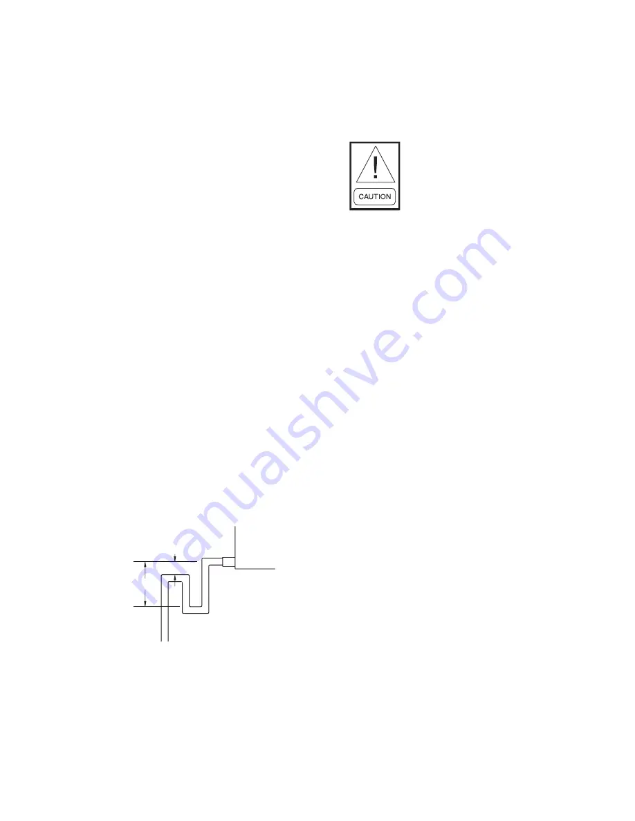
“H” MUST BE AT LEAST
1 INCH PLUS CASING
STATIC PRESSURE

H

X

“X” MUST BE AT
LEAST 1 INCH

Condensate Trap

Trap detail for positive cabinet 

static pressure

Содержание TCSC Series

Страница 1: ...INSTALLATION OPERATION MAINTENANCE FAN POWERED SENSIBLE COOLING VAV TERMINALS Form 130 13 NOM8 1021 MODEL TCSC New Release...

Страница 2: ...SERVICE AND CLEARANCE REQUIREMENTS 12 CHILLED WATER COIL CONNECTIONS 17 HOT WATER COIL CONNECTIONS 21 VALVE PACKAGE COIL CONNECTIONS 26 INSPECTION AND STARTUP CHECKLIST 32 MAINTENANCE 33 FACTORY PROV...

Страница 3: ...age to other equipment and or environmental pollution Usually an instruction will be given together with a brief explanation NOTE is used to highlight additional information which may be helpful to yo...

Страница 4: ...eaters may start automatical ly Disconnect all power and control circuits prior to servicing to avoid burns Check that rigging and lifting equip ment can safely support the equipment assembly and comp...

Страница 5: ...g instructions Check for adequate ventilation so fumesdonotmigratethroughductwork to occupied spaces when welding or cutting around the equipment Do not work on damper until associ ated actuator is di...

Страница 6: ...decrease to the point at which a decrease in primary air will not maintain the desired temperature the reheat will be activated to increase the discharge air temperature INSTALLATION Do not use airflo...

Страница 7: ...INTO AIR VALVE INLET COLLAR When making ductwork connection to air valve inlet collar and insulating air valve inlet take caution not to damage or remove the flow sensor connections which are vital to...

Страница 8: ...p 2 Remove Retaining Screws And Carefully Remove The Auxiliary Drip Pan From The Drip Pan Step 2 Visually Locate Drip Pan Retention Studs Step 1 Locate Drip Pan Retention Clip Press Upward Until Clip...

Страница 9: ...tions Toxic residues and loose particles resulting from manufacturing and field piping techniques such as joint compounds soldering flux and metal shavings may be present in the unit and the piping sy...

Страница 10: ...ompatibility All internal components should be checked for shipping damage and all electrical connections should be tightened to minimize problems during start up Any devices such as thermostats that...

Страница 11: ...are utilized refer to the applicable Operation Manual for start up and balancing information Check that all electrical work is finished and properly terminated Check that all electrical connections a...

Страница 12: ...Inches millimeters All dimensions 1 4 6mm 2 Left Hand unit shown Right Hand unit opposite 3 Standard Electrical Enclosure is integrated into unit side Includes 4 knockouts on 2 sides Provide sufficien...

Страница 13: ...NAL FILTER REMOVAL SIDE ACCESS NOTES 1 All dimensions in Inches millimeters All dimensions 1 4 6mm 2 Left Hand unit shown Right Hand unit opposite 3 90 degree Electrical Enclosure is perpendicular to...

Страница 14: ...OPTIONAL FILTER REMOVAL SIDE ACCESS NOTES 1 All dimensions in Inches millimeters All dimensions 1 4 6mm 2 Left Hand unit shown Right Hand unit opposite 3 Standard Electrical Enclosure is integrated in...

Страница 15: ...M ACCESS OPTIONAL FILTER REMOVAL SIDE ACCESS NOTES 1 All dimensions in Inches millimeters All dimensions 1 4 6mm 2 Left Hand unit shown Right Hand unit opposite 3 90 degree Electrical Enclosure is per...

Страница 16: ...ACCESS DISCHARGE END VIEW B 21 533 3 76 SIDE VIEW NOTES 1 All dimensions in Inches millimeters All dimensions 1 4 6mm 2 Left Hand unit shown Right Hand unit opposite 3 Standard Electrical Enclosure s...

Страница 17: ...3 8 COILS Unit Type Coil Rows A B C 7 10 2 5 127 3 5 8 92 2 3 4 70 3 5 127 3 5 8 92 1 7 8 48 4 5 127 4 1 2 114 1 7 8 48 12 15 20 23 2 6 152 3 5 8 92 2 3 4 70 3 6 152 3 5 8 92 1 7 8 48 4 6 152 4 1 2 1...

Страница 18: ...nnection Size 5 8 ODM 1 2 NOM 3 8 COILS Unit Type Coil Rows A B C 7 10 6 5 127 6 1 4 158 1 7 8 48 8 5 127 8 202 1 7 8 48 12 15 20 23 6 6 152 6 1 4 158 1 7 8 48 8 6 152 8 202 1 7 8 48 DIMENSIONS ARE IN...

Страница 19: ...4 70 3 5 127 3 7 8 98 1 3 4 45 4 5 127 5 127 1 3 4 45 12 15 20 23 2 6 152 3 7 8 98 2 3 4 70 3 6 152 3 7 8 98 1 3 4 45 4 6 152 5 127 1 3 4 45 DIMENSIONS ARE IN INCH MM FORMAT DRAWING NO TITLE REV SHEE...

Страница 20: ...6 5 127 7 1 8 181 1 3 4 45 8 5 127 9 1 4 235 1 3 4 45 12 15 20 23 6 6 152 7 1 8 181 1 3 4 45 8 6 152 9 1 4 235 1 3 4 45 DIMENSIONS ARE IN INCH MM FORMAT DRAWING NO TITLE REV SHEET DATE ALL DRAWINGS A...

Страница 21: ...s 3 8 Coil A B C D 7 10 1 5 7 8 150 3 1 8 78 1 25 4 3 8 111 2 5 7 8 150 3 1 4 82 7 8 22 4 3 8 111 3 5 7 8 150 3 1 4 82 1 3 4 44 4 3 8 111 4 5 7 8 150 4 1 8 104 2 5 8 66 4 3 8 111 15 20 23 1 7 1 4 185...

Страница 22: ...All dimensions may vary in 1 2 13mm Metric values are soft conversion 3 All drawings are subject to change without notice 4 Connection Size 5 8 ODM 1 2 NOM 5 This sheet applies to single circuit coil...

Страница 23: ...COIL ONLY Unit Size Coil Rows 1 2 Coil A B C D 7 1 5 5 8 143 3 1 8 79 1 26 4 3 8 111 3 5 5 8 143 3 1 2 87 2 1 8 55 4 3 8 111 4 5 5 8 143 4 1 2 115 3 1 4 82 4 3 8 111 10 1 5 5 8 143 3 1 8 79 1 26 4 3 8...

Страница 24: ...re soft conversion 3 All drawings are subject to change without notice 4 Connection Size 1 2 ODM 1 2 NOM 5 This sheet applies to single circuit coils only For multiple circuit coils refer sheet no 1 F...

Страница 25: ...vary in 1 2 13mm Metric values are soft conversion 3 All drawings are subject to change without notice 4 Connection Size 5 8 ODM 1 2 NOM 5 This sheet applies to two row two circuit only For multiple...

Страница 26: ...age components 4 Dimensions indicate space requirement for valve package install Additional service space requirements depend on option selections 5 Valve package support structure can be removed 6 SS...

Страница 27: ...alve package components 4 Dimensions indicate space requirement for valve package install Additional service space requirements depend on option selections 5 Valve package support structure can be rem...

Страница 28: ...components 4 Dimensions indicate space requirement for valve package install Additional service space requirements depend on option selections 5 Valve package support structure can be removed 6 SS fle...

Страница 29: ...alve package end point dimensions are fixed value regardless of selected valve package components 4 Dimensions indicate space requirement for valve package install Additional service space requirement...

Страница 30: ...ected valve package components 4 Dimensions indicate space requirement for valve package install Additional service space requirements depend on option selections 5 Valve package support structure can...

Страница 31: ...d valve package components 4 Dimensions indicate space requirement for valve package install Additional service space requirements depend on option selections 5 Valve package support structure can be...

Страница 32: ...late All Piping as Required Connect Supply and Return Pipe to Correct Coil Connections 4 DUCTWORK CONNECTIONS Install Ductwork Fittings Grilles as Required Proper Supply Return Grille Types Sizes Used...

Страница 33: ...an one source of power may be present Discon nect lock out and tag out all power sources to avoid electrocution or shock hazards Motor Blower Assembly Fan powered terminal unit motors are equipped wit...

Страница 34: ...te personal protective equipment 3 Gain access to coil either through ductwork or coil access panel HW coil only 4 Use soft brush and vacuum to remove loose debris from sides of coil 5 Straighten any...

Страница 35: ...he heater back on when the elements have cooled down Should the secondary one time trip limit switch trip it will need to be replaced with a limit switch of the same rating Optional secondary manual r...

Страница 36: ...ct power to unit at main panel 2 Clip switch bracket onto side of pan at low end and press firmly into place ensuring switch wires are positioned up ensure float moves freely 3 Secure bracket into sid...

Страница 37: ...level reaches a point even with the electrical contacts Sensitivity may be adjusted by sliding the sensor assembly up or down along the side of the pan if necessary The sensor must be powered with 24...

Страница 38: ...RV rating as that furnished from or recom mended by the factory Optional 1 and 2 pleated filters are available and can be used in this unit 1 or 2 filter clips can be purchased and will need to be use...

Страница 39: ...NIT SIZE HEATING COIL FACE AREA COOLING COIL FACE AREA NOMINAL FILTER SIZES 1 THROWAWAY FACE AREA 2 THROWAWAY FACE AREA 1 PLEATED GROSS MEDIA AREA 2 PLEATED GROSS MEDIA AREA 07 0 83 0 08 2 69 0 25 1 1...

Страница 40: ...n wheel Align and tighten Motor SCR set too low Readjust motor speed SCR Low Coil Capacity Incorrect airflow Check fan operating conditions Incorrect GPM Check water pumps valves and lines for obstruc...

Страница 41: ...HES W G AIRFLOW CFM SIZE 0407 0410 SIZE 0507 0510 SIZE 0815 0820 0823 SIZE 1015 1020 1023 SIZE 0607 0610 0615 0620 0623 VALVE CALIBRATION CHARTS APPLICABLE CALIBRATION CHARTS ARE AFFIXED TO EACH UNIT...

Страница 42: ...l Max 100 10 0 VDC High 75 8 0 VDC Med 50 6 0 VDC Low 25 4 0 VDC Low Min 13 3 0 VDC Min 6 2 5 VDC 43 10072 02 Rev A FOR REFERENCE ONLY REFER TO UNIT LABEL FOR UNIT SPECIFIC FAN CALIBRATION Max High M...

Страница 43: ...5 0610 109 16 20 24 28 31 35 39 50 58 26 0615 151 19 24 30 35 40 50 60 75 85 28 0620 157 23 30 37 43 40 50 60 75 85 28 0623 159 23 30 37 43 40 50 60 75 85 28 0815 153 19 24 30 35 40 50 60 75 85 28 082...

Страница 44: ...identification 1 Complete unit model number 2 Unit hand connection right or left hand while facing the direction of airflow at the inlet 3 Complete part description including any part numbers On warra...

Страница 45: ...TL MAP1810 0P Quick Start Guide MAP Gateway User Guide MAP Access Portal Gateway Mobile Access Portal MAP Gateway Installation Operation and Maintenance Thermostat Wall Sensors BTN 041 141 241 Zone W...

Страница 46: ...Catalog 130 13 NOM8 1021 New Release 2021 Johnson Controls P O Box 423 Milwaukee WI 53201 www johnsoncontrols com...

Отзывы: