background image


4

    M9106-xGx-2 Series Electric Non-Spring Return Actuators Installation Instructions 

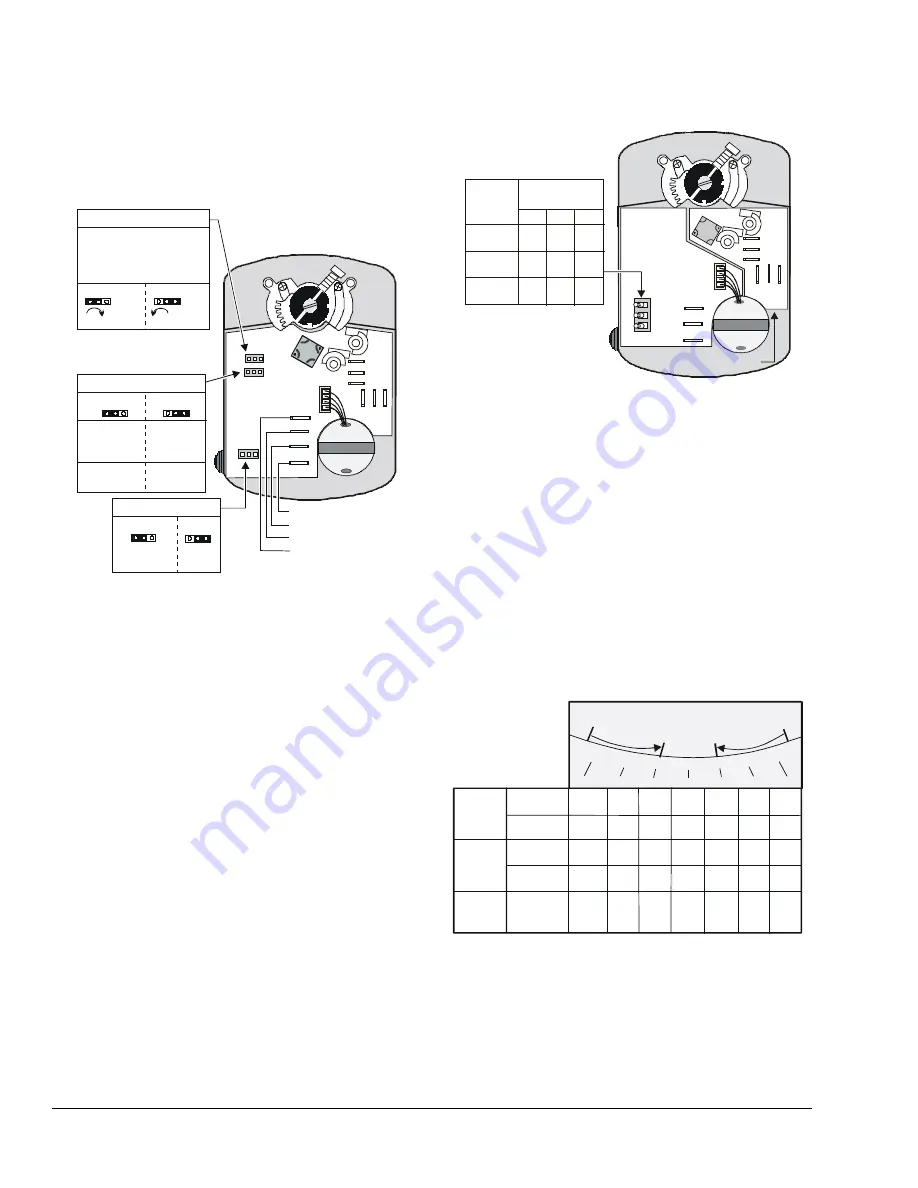
GGx Models 

The M9106-GGx-2 proportional actuators are 
factory set for Direct Acting (DA) mode with 
Jumper W1 in the DA position. Remove Jumper W1 
and place it in the RA position. (See Figure 7.) 

(CW) DA

(CCW) RA

NC2
NO2

C2

C

1

N

C

1

N

O

1

FB

VDC/mA

+24

COM

Jumper W3

Factory Set

VDC

mA

Jumper W2

Jumper W1

Factory Set

Input

Input

0-10 VDC
0-20 mA 

2-10 VDC
4-20 mA

Feedback

0-10 VDC

2-10 VDC

Direct Acting (DA)

Reverse Acting (RA)

Rotation Direction

with Increasing Signal

Factory Set

Note: Jumper W1 is not
          available on the
          floating models.

Common
+24 VAC Power
VDC/mA
Feedback Output


Figure 7: Calibrating the GGx Models 

Jumpers (GGx Models) 

The M9106-GGx-2 proportional actuators are 
factory set with Jumper W2 in the 0 to 10 VDC position 
and Jumper W3 in the VDC position. 

The VDC/mA terminal is the control input signal. 
Jumper W3 must be in the VDC position for 
voltage input and in the mA position for current input. 
The FB Terminal is the feedback output. (See 
Figure 7.) 

Mode Switches (IGx Models) 

The M9106-IGx-2 models offer adjustable rotation 
times of 1, 1.5, 2, 5.5, and 11 minutes (factory set for 
1 minute). Switch settings determine the rotation time 
of the IGx models. Refer to Figure 8 to position the 
mode switches for the desired rotation time. 

NC2
NO2

C2

C

1

N

C

1

N

O

1

Time

(Minutes)

1.0
1.5
2.0
5.5

11.0

1.0

Off
On

Off
On

Off
On

A

B

C

Off
Off

Off
Off

Off
Off

On
Off
On
On

On
On

Mode

Switch Settings

A
B
C

Note: The IGA models have Board 1, and the IGC models
          have both Board 1 and Board 2.

Board 1

Board 2

COM

CW

CCW

Off  On


Figure 8: Mode Switch Settings on IGx Models


The 1-, 1.5-, and 2-minute settings are ideal for on/off 
and floating applications, and replace the 
M9104-xGx-2 1.5-minute models. The 5.5- and 
11-

minute settings are replacements for the 35 lb∙in 

(4 

N∙m) EDA-2040 and the ATP-2040 models. 

Feedback Signal 

The feedback signal will vary with a change to the 
rotation range. For the GGA and GGC models, a 
change to the rotation range changes the feedback 
signal and the operating range proportionally. For the 
AGF model, resistance feedback is reduced 
corresponding to the reduced rotation range. (See 
Figure 9.) 

90°

90°

0.0V

2.0V

10.0V

8.7V  7.3V

6.0V 4.7V

3.3V

10.0V

8.3V

6.7V 5.0V 3.3V 1.7V

75°

75°

60°

60°

45°

45°

30°

30°

15°

15°

Rotation Range

2-10V

Feedback

0-10V

Feedback

Direct

Acting

10.0k

6.7k 

1.7k

0

8.3k 

0-10k ohms

Feedback

5.0k  3.3k 

Direct or

Reverse

Acting

2-10V

Feedback

Reverse

Acting

0-10V

Feedback

0.0V 1.7V

3.3V 5.0V 6.7V

8.3V 10.0V

10.0V

8.7V

7.3V

6.0V

4.7V

3.3V

2.0V

Set Screw

Adjustment

Set Screw

Adjustment

Note: 

0-10k ohms feedback is available on AGF models. 

0-10V is available on GGA and GGC models.


Figure 9: Nominal Feedback Signal Relative to 

the Rotation Range


Содержание M9106 Series

Страница 1: ... alarme ou des dispositifs de sécurité ou de limitation ayant une fonction d avertissement ou de protection en cas de défaillance ou de dysfonctionnement du M9106 xGx 2 Series actuator Parts Included M9106 xGx 2 actuator M9000 160 anti rotation bracket two No 12 24 x 1 2 in self tapping hex washer head screws spade terminals Special Tools Needed drill with a 3 16 in No 15 4 57 mm drill bit 5 16 in...

Страница 2: ...hten the mounting screws to avoid stripping the threads 8 Secure the coupler to the shaft using a 5 16 in 8 mm square socket or 3 8 in 10 mm 12 point socket to tighten the coupler set screw against the damper shaft See Figure 1 9 Continue tightening the coupler set screw to achieve a torque of 150 to 180 lb in 17 to 20 N m Note Keep the actuator parallel to the mounting surface while tightening th...

Страница 3: ...river to loosen the end stop set screw on the actuator that is closest to the stop gear and move it in its slot so it is tight against the stop gear See Figure 5 IMPORTANT Do not remove the end stop set screws as this could interfere with the actuator s operation 4 Repeat Steps 1 through 3 to set the desired maximum rotation position 5 Tighten both end stop set screws to a minimum of 25 lb in 2 8 ...

Страница 4: ...tches for the desired rotation time NC2 NO2 C2 C1 NC1 NO1 Time Minutes 1 0 1 5 2 0 5 5 11 0 1 0 Off On Off On Off On A B C Off Off Off Off Off Off On Off On On On On Mode Switch Settings A B C Note The IGA models have Board 1 and the IGC models have both Board 1 and Board 2 Board 1 Board 2 COM CW CCW Off On Figure 8 Mode Switch Settings on IGx Models The 1 1 5 and 2 minute settings are ideal for o...

Страница 5: ...ar or drive time on the motor for the AGx models use a controller and or software that provides a time out function to remove the signal at the end of rotation stall The GGx and IGx models have an auto shutoff to avoid excessive wear or drive time on the motor Through the Conduit Openings Depending on the M9106 model selected one or both conduit openings are used 1 Loosen the cover screw and remov...

Страница 6: ...3 Note At this point the normally closed contact closes and the normally open contact opens See Auxiliary Switches in Figure 10 Switch S2 To change the angle of Switch S2 to 70 refer to Figure 13 and proceed as follows 1 Press and hold the gear release Using the 0 to 90 nodule guides rotate the coupler until the center of the coupler set screw is at 70 2 Rotate Switch S2 CW and align the edge of t...

Страница 7: ... 35 lb in 4 N m Cycles 100 000 full cycles 2 500 000 repositions rated at 53 lb in 6 N m Audible Noise Rating 35 dBA maximum at 1 m Rotation Range Adjustable from 30 to 90 CW or CCW Rotation Time IGx Adjustable with switch settings Factory set for 1 minute See Figure 12 60 90 120 330 or 660 seconds 1 1 5 2 5 5 or 11 min at 60 Hz and 72 108 144 396 or 792 seconds 1 2 1 8 2 4 6 6 or 13 2 minutes at ...

Страница 8: ...s Installation Instructions Building Efficiency 507 E Michigan Street Milwaukee WI 53202 Metasys and Johnson Controls are registered trademarks of Johnson Controls Inc All other marks herein are the marks of their respective owners 2014 Johnson Controls Inc ...

Отзывы: