501562-UIM-A-0909
Johnson Controls Unitary Products
7
CFM SELECTION BOARD SETTINGS
For proper system operation the CFM Selection Board jumpers must be
set properly.
Refer to the Tabular Data Sheet for the recommended air flow settings
for each size condensing unit.
Set the cooling speed per the instructions for the air handler or furnace
by selecting the correct COOL and ADJ taps. Verify the airflow using
the LED display on the CFM selection board.
The HUMIDISTAT jumper must also be removed if a dehumidistat is
installed.
If installed as a communicating system (outdoor, indoor and thermo-
stat), the system will automatically adjust to the optimal airflow settings.
These parameters can also be modified using the communicating ther-
mostat. Refer to the communicating thermostat owner’s manual for this
procedure. Manual setting of the airflow jumpers on the ID equipment
is not necessary with the communicating thermostat.
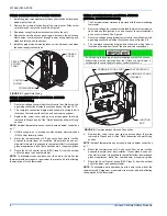
FIGURE 7:
CFM Selection Board
HEA
T
DELA
Y
COOL
ADJUST
A
B
C
D
A
B
C
D
LED
2
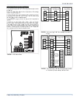
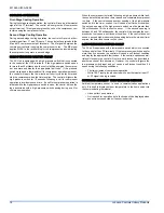
FIGURE 8:
Communicating AC with Communicating Air Handler or
Furnace
FIGURE 9:
Communicating AC with Non-Communicating Air Handler
or Furnace using Communicating Interface Control
R
C
Y1
Y2
Touch Control
Communicating
Control
Air Handler/Furnace
Communicating
Control
Air Conditioner
Communicating
Control
GND
or C
GND
or C
B-
R
A+
GND
or C
GND
or C
B-
R
A+
GND
or C
GND
or C
B-
R
A+
R
C
Y1
Y2
HUM
W2
DHUM
W
G
C
R
O
Y
Y2
HUM
W2
DHUM
W
G
C
R
O
Y
Y2
Touch Control
Communicating
Control
Communicating
Indoor
Interface Control
Non-Communicating
Indoor Unit
Air Conditioner
Communicating
Control
Wire per
non-comm.
installation
manual
Assume that
connections
are from
thermostat
GND
or C
GND
or C
B-
R
A+
GND
or C
GND
or C
B-
R
A+
GND
or C
GND
or C
B-
R
A+


