


25
8
130mm
HEATER
DEFLCTOR PLATE
Fig.4
Pilot Burner Assembly
Thermocouple
Pilot Burner
Electrode
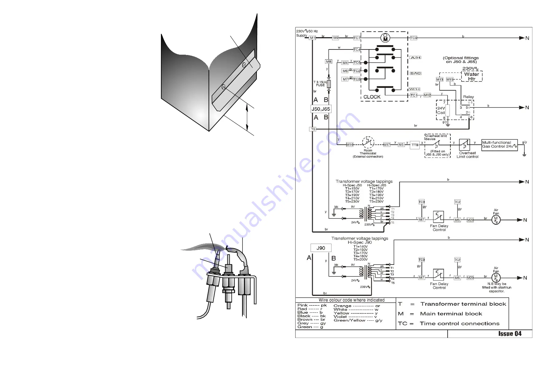
Fig. 7b
Non-Modairflow Functional Diagram
6.
COMMISSIONING
6.1
PREPARATION:
6.1.1
Ensure that:
a.
Gas and Electrical supplies are
OFF
.
b.
Filter, fan and fan compartments are free from
obstructions.
c.
All registers or grilles are open and conform to
design specifications.
d.
Return, relief and ventilation air installations are
adequate.
6.1.2 SETTING FAN SPEED (NON MODAIRFLOW MODELS ONLY):
6.1.2.1 Remove air filter and chamber door.
6.1.2.2 Ensure fan control is set to “100
o
” OFF and “40
o
” DIFF
6.1.2.3 Ensure overheat (limit) control is set to “200
o
F” This control is not to be set to any other setting!
6.1.2.4 Refit fan chamber door and air filter.
6.2
SYSTEM BALANCING:
6.2.1
Set the Air Heater electrical supply ON.
6.2.2
Set the ‘SUMMER AIR CIRCULATION’ switch to ‘
ON
’.
6.2.3
Balance the ducting system to provide the required volume proportions at the
warm air outlets.
NOTE:
If the system includes ceiling diffusers, air velocities through these should be NOT
LESS THAN 1.5m/s (300 ft/min), except for very small rooms (i.e., bathrooms
etc.). Outlet faces may require partial blanking in order to achieve this.
6.2.4
Set the ‘SUMMER AIR CIRCULATION’ switch to ‘
OFF
.
6.3
IGNITION OF PILOT AND MAIN BURNERS:
WARNING:
If the Pilot Burner is extinguished either intentionally or unintentionally, no
attempt should be made to relight the gas for a minimum of 3 minutes. Ensure
that the Electrical supply, Time Control and Selector switches are set to
‘
OFF
’
.
6.3.1
Set the Thermista-stat/room thermostat to its lowest or
OFF
setting.
6.3.2
On the Multifunctional Control, remove the Outlet Pressure test point cover,
and a fit pressure test gauge (refer Fig. 5).
6.3.3
Turn the heater Gas supply
ON
, test for gas soundness and purge the whole
gas pipe as described in BS 6891.
6.3.4
Referring to Fig .5, press and hold the OPERATING CONTROL, and whilst
observing the Pilot Burner, repeatedly press the Piezo igniter button until the
Pilot Burner ignites.
6.3.5
After 20 seconds release the OPERATING CONTROL and let it spring out; ensure that the Pilot Burner remains alight.
If the Pilot Burner extinguishes, rotate the OPERATING CONTROL clockwise to the ‘l’ position and ensure that the
OPERATING CONTROL is fully reset. Wait three minutes and repeat steps 6.3.4 and 6.3.5 until Pilot Burner remains
alight.
Fig. 3
Deflector Plate Fitted


