VENTILATED
Low level grille
288cm
2
(44in
2
)
FROM INSIDE
BUILDING
High level grille
144cm
2
(22in
2
)
VENTILATED
Low level grille
144cm
2
(22in
2
)
FROM OUTSIDE
BUILDING
High level grille
72cm
2
(11in
2
)
Table 1: Minimum Effective Areas
4.
DUCT SYSTEM
(See British Design Manual - Gas fired Warm Air Heating)
4.1
RETURN AIR
4.1.1
All return air shall be POSITIVELY ducted from outside the compartment to the top of the unit via a return air
duct, or if appropriate, using a J & S Side Return Air Kit, and mechanically secured. It is recommended that the
return air duct be not routed directly from the main living area, but from a convenient central area serving the
remainder of the dwelling.
4.1.2
The return air system should be constructed of fire-resistant material. The flue shall not be run through an area
serving as a return air path. It is extremely important that the correct size of return air grilles and ducting is used.
For heaters on maximum output the return air duct size should not be less than the equivalent of 250mm x 200mm
(10" x 8"). If flexible duct is used the duct diameter should not be less than 300mm (12") dia. The return air
grille should have a free area of not less than 860cm
2
(137in
2
).
4.1.3
An adequate and unobstructed return air path is essential from areas not served by a directly ducted return and to
which warm air is delivered. All such rooms should be fitted with relief grilles which have a free area of
0.0088m
2
/kW (1in
2
/250Btu/h) of heat supplied to the room. The only exceptions are kitchens, bathrooms and
WC.’s.
4.1.4
The return air duct should allow for ease of removal for access to the flue.
4.1.5
All duct work in the room or internal space in which the heater is installed shall be mechanically secured, and
sealed with ducting tape.
4.2
WARM DELIVERED AIR
4.2.1
All duct work, including riser ducts, should be fully insulated with 50mm (2in) fibreglass or similar. If short
extended duct runs are taken below floor level these should be similarly insulated, and in addition wrapped with a
sound vapour proof barrier, and protected from crushing.
4.2.2
The duct system should be carefully designed (as given in the guidelines in the British System Design Manual) to
suit the needs of its specific heating requirements and building layout. The type of duct system, (i.e. radial/
extended plenum/stepped) should be installed using the least number of fittings to minimise airflow resistance.
The base duct, which equalises the air pressure to supply ducts, shall be constructed to support the weight of the
heater, which shall be secured to the plenum with screws on at least two sides, and sealed using self-adhesive
foam strip, ducting tape or sealing compound. All ducting and blanking plates shall be mechanically secured and
sealed.
5.
INSTALLATION REQUIREMENTS
Note: For circulator Installation Instructions, refer to the relevant instructions provided with the circulator.
5.1
FLUES
(see British Standards BS 5440 Pt. 1 Flues)
5.1.1
All joints shall be soundly sealed.
5.1.2
The flue should be kept as short and warm as possible.
5.1.3
Sufficient support brackets shall be installed to bear the weight of the total flue system.
5.1.4
The spigot connection of the heater draught diverter will accept internally the spigot end of a non-asbestos flue
to BS 567 or twin wall metal flue to BS 715 of nominal 100mm (4in) diameter.
5.1.5
A split collar should be fitted to provide for flue maintenance or inspection.
5.1.6
The flue shall be in accordance with the Building Regulations and British Gas Materials and Installations
specification (3rd edition) with regard to clearance and shielding from combustible materials.
5.1.7
All materials shall be in accordance with Building Regulations requirements.
3
18
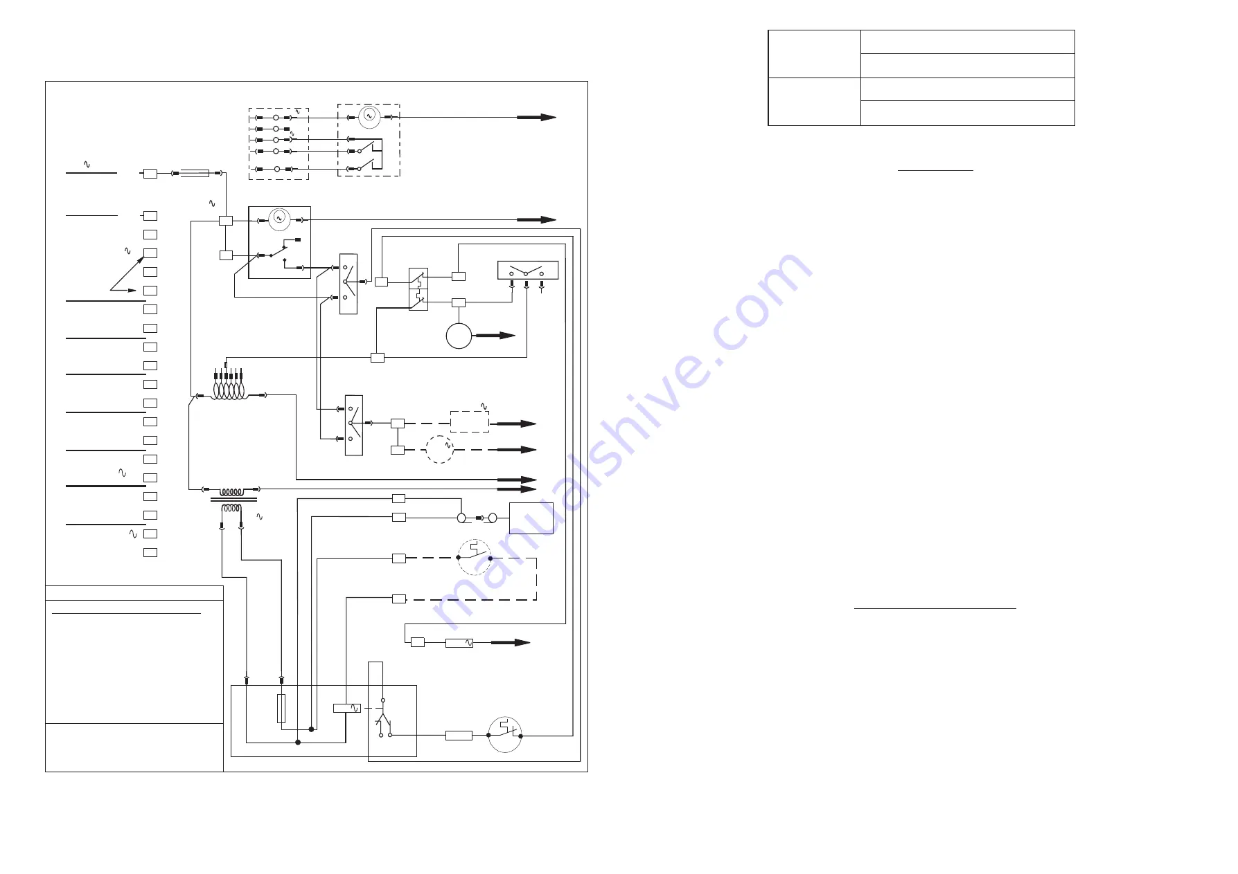
Fig. 6, FUNCTIONAL DIAGRAM
4
13
18
14
17
12
19
8
7
FELV * Connection
20
10
6
N
Timed
230V
Cont.
A
3
4
5
6
7
8
9
10
11
12
13
14
15
16
17
18
19
20
2
N
N
N
T
L
N
24V
0V
GE
L
L
Room Thermostat
Water Heater
(Optional)
Water Pump
(Optional)
Limit Switch
Multi-functional
Control 230V
Fan Delay
Control
Cleanflow
(Optional)
Wire colour code where indicated
*FELV Functional Extra-Low Voltage
NOTES:-
red-----------r
blue---------b
black-------bk
brown------br
white-------w
grey-------gy
orange---or
violet------v
yellow-----y
black/white------bk/w
purple/red-------p/r
green/yellow----g/y
N
N
N
N
N
N
CLOCK
C4
C5
C3
Link
gy
gy
b
r
r
bk
w
br
br
br
br
br
bk
p/r
p/r
y
r
y
v
r
bk
bk
br
r
or
r
r
r
bk
br
br
r
bk
1
230V 50Hz
Supply
L
br
S4
S6
S5
T
1
0
AIR
HTR.
S7
S9
S8
T
1
0
WATER
HTR.
L
Voltage
Selector
TX1
Summer
Air Flow
Limit
Switch
Fan Delay
Control
Fan
230V
PUMP
N
230V
(Optional)
(Optional)
(See
note)
(Optional)
SW
Comm.
n/o
24V
Cleanflow
Air
Cleaner
Water
Htr
T500mA
Relay Module
24V Thermostat
(Not Fitted)
15
230V
Multi-functional Control
N
br
br
b
Butt
Connector
br
w
Spill
Switch
(TTB)
or
or
S3
ON
S1
OFF
S2
1
1
0
EXTERNAL PROG.
OPTION
NO CLOCK
OPTION
Park S8 when no
water htr. or
for ext. prog.
N
C1
230V
N
WH
Timed
230V Cont.
AH(S5)
Timed
C2
C3
C6
S8
CH
WH
230V
Continuous
C2
C1
T3.15A
FUSE
br
M
M
TX2
24V
0V
L
N
Park conns when no
clock fitted or for
external prog.
If Superjan fitted remove red wire link
between terminals 10 &12


