13
8.5
MULTIFUNCTIONAL CONTROL REMOVAL:
8.5.1
Remove the Burner and Controls Assembly as detailed in 8.2
8.5.2
Disconnect the Thermocouple at the Multifunctional Control, avoiding damage to the capillary.
8.5.3
Disconnect the Pilot Feed Pipe from the Multifunctional Control.
8.5.4
Disconnect the Multifunctional Control input and output supply feeds.
8.5.5
Refitting or replacement is in reverse order.
NOTE:
When refitting or replacing the Multifunctional Control, the ‘O’ ring seal is to be replaced.
8.6
PIEZO UNIT REMOVAL:
8.6.1
Disconnect the 2 conductors from Piezo unit.
8.6.2
Release the retaining nut and remove the Piezo unit from its mounting bracket.
8.6.3
Refitting or replacement is in reverse order.
8.7
AIR CIRCULATING FAN, REMOVAL AND CLEANING:
8.7.1
Ensure that the electrical supply is isolated.
8.7.2
Remove the appliance louvre door, release the 2 x securing screws and hinge down the fan chamber door.
8.7.3
Disconnect the fan flying leads from the Fan Assembly.
8.7.4
Release the Fan Assembly securing screw and withdraw the Fan Assembly from the Heater cabinet, avoiding
damage to the fan blades.
8.7.5
Remove all dust from both the impeller and motor, taking care to not disturb the balance of the fan.
8.7.6
Refitting or replacement is in reverse order.
8.8
ELECTRICAL ASSEMBLY REMOVAL:
8.8.1
Ensure that the electrical supply is isolated.
8.8.2
Remove the appliance louvre door, release the 2 x securing screws and hinge down the fan chamber door.
8.8.3
Disconnect the following:
a.
Air circulation fan flying leads from the Fan assembly,
b.
230V mains ‘
L
’,
‘
N
’ and ‘
E
’ from connection block terminals ‘
1
’ and ‘
2
’, and
Earth stud
respectively,
c.
Room thermostat connections from connection block terminals ‘
7
’ and ‘
8
’,
d.
Limit Switch from connection block terminals ‘
13
’ and
‘
14
’,
e.
Fan Delay Control from connection block terminals ‘
18
’ and
‘
17
’,
f.
Multifunctional Control from connection block terminals ‘
16
(N) and ‘
15
’ (L),
g.
Water heater from connection block terminals ‘
10
’ (L) and ‘
9
’ (N),
h.
Water Pump from connection block terminals ‘
12
’ (L) and ‘
11
’ (N),
i.
Cleanflow from connection block terminals ‘
19
’ (24V) and ‘
20
’ (0V),
j.
Earth lead from the fan chamber floor,
8.8.4
Disconnect 2 x Spillage monitoring device connections from the terminal block on the fan compartment
diaphragm.
8.8.5
Release the 2 x hinge pins and withdraw the Electrical Assembly, releasing wiring from cable clamps and
grommets as required..
8.8.6
Refitting or replacement is in reverse order.
8.9
TRANSFORMER REMOVAL:
8.9.1
Ensure that the electrical supply is isolated.
8.9.2
Remove the appliance louvre door, release the 2 x securing screws and hinge down the fan chamber door.
8.9.3
Disconnect the conductors from the large Transformer.
8.9.4
Release 2 x screws and nuts securing Transformer to Electrical assembly, and remove Transformer..
8.9.5
Refitting or replacement is in reverse order.
6.2
SYSTEM BALANCING:
6.2.1
Set the Air Heater electrical supply
ON.
6.2.2
Set the SUMMER AIRFLOW switch to ‘
1
’.
6.2.3
Balance the system to provide the required volume proportions at the warm air outlets.
Note:
If the system includes ceiling diffusers, the air through these should be NOT LESS THAN 1.5m/s (300ft/min), except
for very small rooms, (i.e. bathrooms etc.). Outlet faces may require partial blanking in order to achieve this.
6.2.4
Set the SUMMER AIRFLOW switch to ‘
0
’.
6.3
IGNITION OF PILOT AND MAIN BURNERS:
WARNING:
If the pilot light is extinguished either intentionally or unintentionally, no attempt should be made to
relight the gas for a minimum of 3 minutes. Ensure that the electrical supply, Time Control and Selector switches are set to
‘OFF’.
6.3.1
Set the room thermostat to its lowest setting.
6.3.2
On the Multifunctional Control, remove the Inlet Pressure test point cover, and a fit pressure test gauge (refer fig.
4).
6.3.3
Turn the heater Gas supply
ON
, test for gas soundness and purge the whole gas pipe as described in BS 5482
Part 1.
6.3.4
Referring to Fig .4, press and hold the OPERATING CONTROL, and whilst observing the Pilot Burner, repeatedly
press the Piezo igniter button until the Pilot Burner ignites.
6.3.5
After 20 seconds release the OPERATING CONTROL and let it spring out; ensure that the Pilot Burner remains
alight. If the Pilot Burner extinguishes, rotate the OPERATING CONTROL clockwise to the ‘
z
’ position and
ensure that the OPERATING CONTROL is fully reset. Wait three minutes and repeat steps 6.2.4 and 6.2.5 until
the Pilot burner remains alight.
6.3.6
With the Pilot burner lit, depress the OPERATING CONTROL and turn it to the position indicated by the flame
symbol.
6.3.7
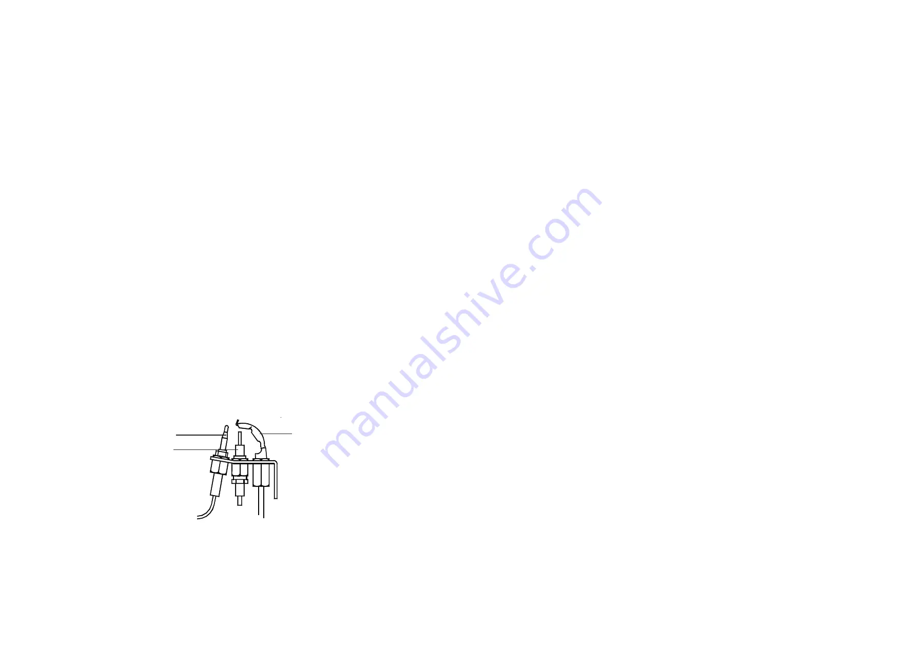
Ensure that the pilot flame envelops thermocouple tip (refer Fig. 3).
6.3.8
Set the Heater Electricity supply
ON.
6.3.9
Set the Time control to the required Heating On periods.
6.3.10 Set the Selector switch to ‘TIMED’.
6.3.11 Set the room thermostat to MAXIMUM.
6.3.12 Ensure that the main burner has now ignited.
6.3.13 Test for gas leakage at the supply, Multifunctional control, Pilot and Main burners using proprietary detection
fluid, sealing any leaks found.
6.3.14 Allow heater to operate for a minimum of 15 minutes to ensure stability.
Fig. 3
PILOT BURNER ASSEMBLY
8
Thermocouple
Electrode
Pilot Burner


