


65
GEN04
Chapter 15 - Adjustments
Power Level Adjustment
Upon start-up, the generator defaults to power level 3 (MIN) and 5 (MAX). The minimum (MIN) power level
is user-settable from power levels 1 to 5. To adjust the power level, depress the UP/DOWN arrow button to
the left of the MIN power level display. Set the power level based on surgeon preference and/or
recommendations provided in the instrument’s package insert (for more information, see Power Levels
section in Chapter 2 – General Description).
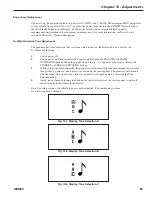
Audible Activation Tone Adjustment
The generator has three activation tone sets from which to choose (the mid-pitch tone is factory set).
To choose another tone:
1
Switch power off.
2
Switch power on. Then immediately depress and hold both the STANDBY and HAND
ACTIVATION buttons. When the graphic shown in Fig. 11-1 appears on the display, release the
STANDBY and HAND ACTIVATION buttons.
3
While in the Tone Selection mode, the generator will automatically sequence through the available
tone pitches. To select a tone, depress any button on the control panel. The generator will return to
Standby mode. The tone chosen will be saved until it is changed again by accessing the Tone
Selection mode.
4
Adjust tone volume by turning the knob on the lower left corner of the control panel. A tone will
sound to indicate the volume level selected.
Note: For safety reasons, the audible tone may not be disabled. The audible tone volume
for alarms cannot be changed.
Fig. 15-1 Display: Tone Selection A
Fig. 15-2 Display: Tone Selection B
Fig. 15-3 Display: Tone Selection C
Содержание ETHICON ENDO-SURGERY HARMONIC 300
Страница 1: ...HARMONIC Generator 300 System Service Manual ...
Страница 2: ...GEN04 ...
Страница 6: ...4 GEN04 Service Manual ...
Страница 10: ...8 GEN04 Service Manual ...
Страница 16: ...14 GEN04 Service Manual ...
Страница 24: ...22 GEN04 Service Manual ...
Страница 26: ...24 GEN04 Service Manual ...
Страница 28: ...26 GEN04 Service Manual ...
Страница 44: ...42 GEN04 Service Manual ...
Страница 50: ...48 GEN04 Service Manual Power Supply Fig 12 5 Power Supply Troubleshooting Flowchart ...
Страница 51: ...49 GEN04 Chapter 12 Hardware Troubleshooting LCD Display Fig 12 6 LCD Display Troubleshooting Flowchart ...
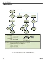
Страница 52: ...50 GEN04 Service Manual Front Bezel Fig 12 7 Front Bezel Troubleshooting Flowchart ...
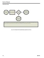
Страница 54: ...52 GEN04 Service Manual Unit Short Test Fig 12 9 Unit Short Test Troubleshooting Flowchart Cont ...
Страница 55: ...53 GEN04 Chapter 12 Hardware Troubleshooting Cooling Fan Fig 12 10 Cooling Fan Troubleshooting Flowchart ...
Страница 58: ...56 GEN04 Service Manual ...
Страница 62: ...60 GEN04 Service Manual ...
Страница 66: ...64 GEN04 Service Manual ...
Страница 68: ...66 GEN04 Service Manual ...
Страница 72: ...70 GEN04 Service Manual ...
Страница 76: ...74 GEN04 Service Manual ...
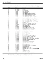
Страница 77: ...75 GEN04 Appendix B GEN04 Main Assembly Drawing ...
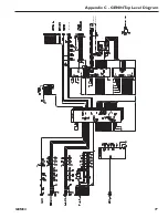
Страница 79: ...77 GEN04 Appendix C GEN04 Top Level Diagram Hand Piece ID Hand Piece Transducer ...


