


47
GEN04
Chapter 12 - Hardware Troubleshooting
Procedures
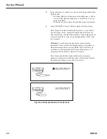
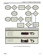
The following sections contain flowcharts that outline procedures to help determine whether the problem that is
occurring is due to a high-level component failure or a failure associated with the Generator Board. Before executing
any of these procedures, remove the Generator’s cover, attach a known good instrument or test tip and power the unit
up. Note: All specifications are +/-10% unless otherwise specified.
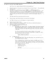
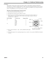
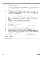
Hand Piece Assembly Receptacle Continuity Test
1
Power down the unit and remove the power cord.
2
Disconnect the wire harnesses from connectors J3 and J4.
3
Measuring between the Hand Piece Receptacle on the front panel and the Generator Board wire
harness connectors, test the continuity of each of the wires according to the pinout table below
(use Figure 12-4 as a reference):
PCB Connector
Connector Wire
Receptacle Pin
J3
Red
1
Yellow
2
Orange
3
Green
4
J4
Brown
5
Black
6
Blue
7
4
If any of the wires measure as “open”, replace the Hand Piece Receptacle
Assembly.
5
Upon visual inspection, if any receptacle pins appear worn, corroded, or loose, replace the Hand Piece Receptacle
Assembly.
Fig. 12-4 Pinout Table
Содержание ETHICON ENDO-SURGERY HARMONIC 300
Страница 1: ...HARMONIC Generator 300 System Service Manual ...
Страница 2: ...GEN04 ...
Страница 6: ...4 GEN04 Service Manual ...
Страница 10: ...8 GEN04 Service Manual ...
Страница 16: ...14 GEN04 Service Manual ...
Страница 24: ...22 GEN04 Service Manual ...
Страница 26: ...24 GEN04 Service Manual ...
Страница 28: ...26 GEN04 Service Manual ...
Страница 44: ...42 GEN04 Service Manual ...
Страница 50: ...48 GEN04 Service Manual Power Supply Fig 12 5 Power Supply Troubleshooting Flowchart ...
Страница 51: ...49 GEN04 Chapter 12 Hardware Troubleshooting LCD Display Fig 12 6 LCD Display Troubleshooting Flowchart ...
Страница 52: ...50 GEN04 Service Manual Front Bezel Fig 12 7 Front Bezel Troubleshooting Flowchart ...
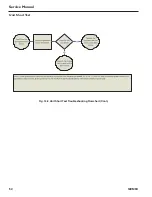
Страница 54: ...52 GEN04 Service Manual Unit Short Test Fig 12 9 Unit Short Test Troubleshooting Flowchart Cont ...
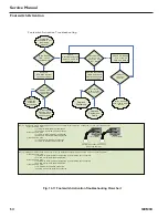
Страница 55: ...53 GEN04 Chapter 12 Hardware Troubleshooting Cooling Fan Fig 12 10 Cooling Fan Troubleshooting Flowchart ...
Страница 58: ...56 GEN04 Service Manual ...
Страница 62: ...60 GEN04 Service Manual ...
Страница 66: ...64 GEN04 Service Manual ...
Страница 68: ...66 GEN04 Service Manual ...
Страница 72: ...70 GEN04 Service Manual ...
Страница 76: ...74 GEN04 Service Manual ...
Страница 77: ...75 GEN04 Appendix B GEN04 Main Assembly Drawing ...
Страница 79: ...77 GEN04 Appendix C GEN04 Top Level Diagram Hand Piece ID Hand Piece Transducer ...


