4 Flow Switch Installation
Flow switch
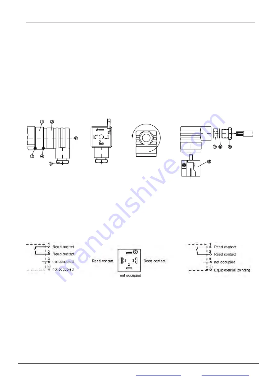
4.2.2 Elbow plug connector EN 175301-803-A
⇒
Loosen the central screw (pos. 6) M3x35 and disconnect the junction box EN 175301-803-A
(pos. 2) from the connector (pos. 1) (Fig. 7).
⇒
Use a screwdriver or similar tool to press out the core (pos. 8) of the junction box (Fig. 8).
⇒
Loosen the screw connection PG 9 (pos. 5, Fig. 9).
⇒
Feed the connecting cable into the junction box via the screw connection (pos. 5), the clamping ring (pos.
10) and the rubber insert (pos. 9) and subsequently connect the wires as displayed in the connection
diagram (see Fig. 11).
⇒
Press the core (pos. 8) until it locks into position in the junction box (pos. 2).
⇒
Tighten the cable gland PG 9 (pos. 5).
⇒
Place the junction box (pos. 2) on the connector (pos. 1) and retighten the central screw (pos. 6).
Fig. 7
Fig. 8
Fig. 9
Fig. 10
⇒
To guarantee the protection class IP 65 according to EN 60529, the applied connecting cable has to have
a sheathing diameter of between 4.5 and 7 mm.
⇒
Furthermore, ensure that all the connector seals (pos. 3, 4 and 9) have been correctly inserted.
Flow switch version VHS.../VKS...
Flow switch version VHS...X
Fig.
11
*To prevent electrostatic charging the VHS…X devices have to be connected to the equipotential bonding via
the elbow plug connector.
Page 9 of 15
Copyright © Jlso Tec Trade GmbH
JLSO Tec Trade GmbH
In den Birken 98
Fon:
+49 (0)
6369 230 9961
Fax:
+49 (0)
6369 230 9963
https://jlso-tec-trade.de
Daniel
H.
Meckel
D-66999
Hinterweidenthal


