5 Adjusting the Switching Unit
Flow switch
5.3 Flow switch version VHS... , VKS... and VK3...
⇒
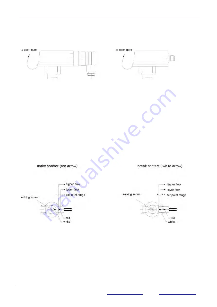
In order to adjust the switching unit, open the cover of the switching head (Fig. 15)
(not required for VK3...)
Fig.15
⇒
Subsequently loosen the locking screw (2.5 hexagon socket screw for the brass and stainless steel
version or recessed head screw for the plastic version) and position the switching unit until the red or
white arrow are visible at the entry of the switching contact guide for a desired make contact (Fig. 16) or
break contact (Fig. 17) respectively.
⇒
The fine adjustment of the switching point can be carried out on the basis of the arrow length:
Movement towards the arrow head: Switching point is set to lower flow rate.
Movement towards the arrow tail: Switching point is set to higher flow rate.
⇒
Carefully retighten the locking screw.
⇒
We recommend you to use lacquer/threadlocker to secure the locking screw of the switching unit after
carrying out individual adjustments.
⇒
Close the cover until it locks into place (not required for VK3...).
Adjustment of the switching unit is not required if a desired ex works switching point setting has been agreed
with the customer.
Fig. 16
Fig. 17
Page 12 of 15
Copyright © Jlso Tec Trade GmbH
JLSO Tec Trade GmbH
In den Birken 98
Fon:
+49 (0)
6369 230 9961
Fax:
+49 (0)
6369 230 9963
https://jlso-tec-trade.de
Daniel
H.
Meckel
D-66999
Hinterweidenthal


