Jinko Solar Co., Ltd
No.1, Jinko Road, Shangrao Economic Development Zone Shangrao City,
Jiangxi Province, 334100, P.R. China
[email protected]
Jinko Solar
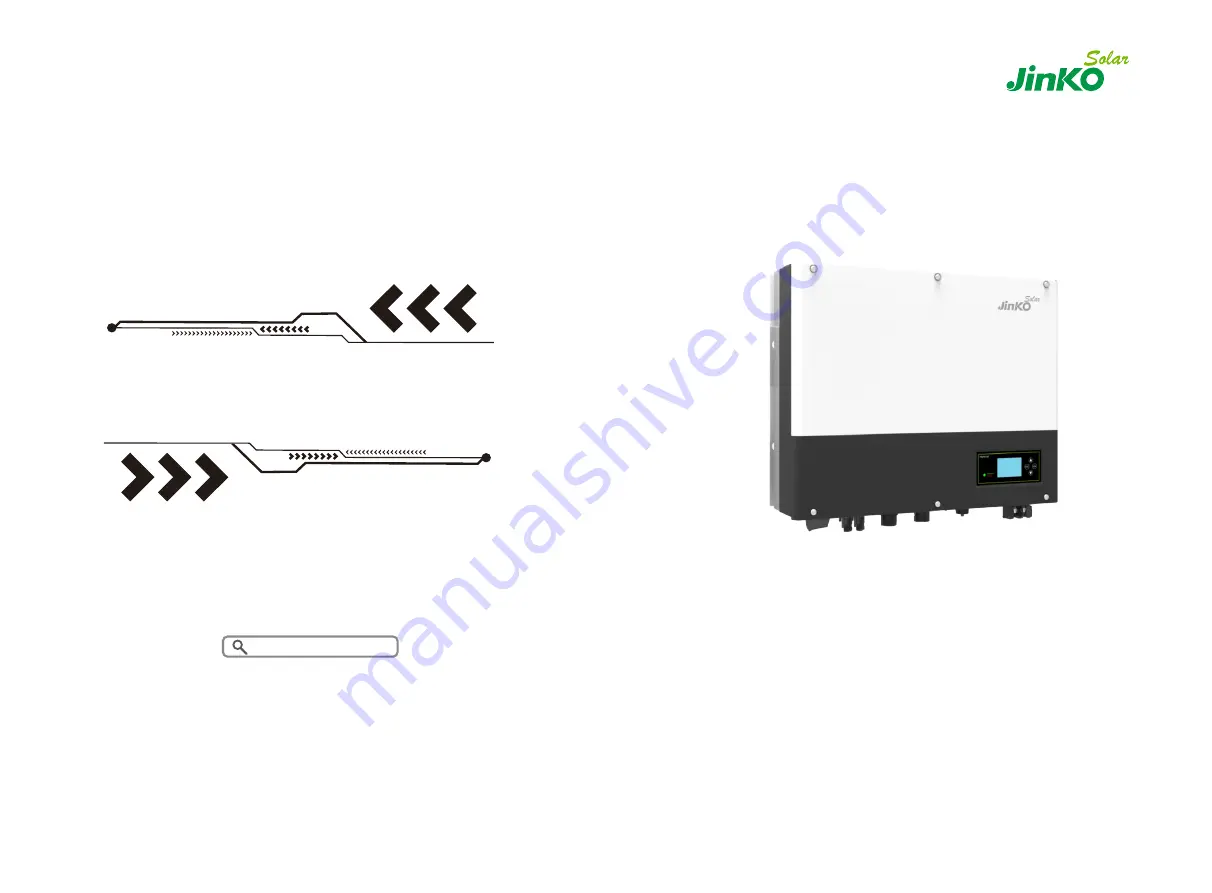
JKS-3~6HLVS-ABI Series User Manual
W:
www.jinkosolar.com
Страница 1: ...ko Solar Co Ltd No 1 Jinko Road Shangrao Economic Development Zone Shangrao City Jiangxi Province 334100 P R China BESS_AU Jinkosolar com Jinko Solar JKS 3 6HLVS ABI Series User Manual W www jinkosolar com ...
Страница 2: ...roduction On The JKS Inverter Safety 3 1 JKS 3 6HLVS ABI Series Inverter 3 2 Label Explanation 3 3 Size and Weight 3 4 The Advantage of The Unit of JKS Product Description Installation 5 1 Basic Installation Requirements 5 2 Installation Requires Tools and RJ 45 Terminal Sequence of The LAN Line 5 3 Installation Instructions 5 4 Grounding Connection Unpacking ...
Страница 3: ...Maintenance and Cleaning 11 1 Dismantling The Inverter 11 2 Package and Transport JKS Inverter 11 3 Storing JKS Inverter 11 4 Disposing of The JKS Inverter Decommissioning Manufacturer Warranty Product Specification 12 1 JKS 3 6HLVS ABI SeriesMachine Product Specification 13 2 DC Input Terminal Parameter 13 3 Torque 13 4 Appendix Certificate Contact 6 7 8 9 10 11 12 13 14 Fault Removal 9 1 Trouble...
Страница 4: ...nal wireless communication does not require line of sight between the devices and it is selective purchasing JKS 3 6HLVS ABI Series is used to store energy generated by the photovoltaic cell panels or energy from grid if it is allowed in the battery also energy can be sent to power grid through JKS 3 6HLVS ABI for self consumption or when Grid power is lost JKS 3 6HLVS ABI can be used as backup po...
Страница 5: ...an t work normally 2 Please read this manual carefully before the installation the product warranty may be voided if the inverter is not installed according to the instructions of this manual for installation and cause equipment damage 3 All the operation and connection please professional electrical or mechanical engineer 4 During installation please don t touch the other parts within the box 5 A...
Страница 6: ...ive or negative ground connection please contact with Jinko for technical support before installation The system chart of JKS 2 2 Safety Measure Risk of burns on the parts shell of JKS inverter During the work Cover shell around radiator is likely to be hot JKS inverter ground connection Please ensure JKS inverter ground connection is reliable for make sure people s safety Risk of high voltage JKS...
Страница 7: ...r the DC lid Protective conductor terminal Direct Current DC Alternating Current AC The machine complies with the requirements of the applicable CE guidelines Refer to the operating instructions 3 Product Description 3 1 JKS 3 6HLVS ABI Series Inverter Marks of JKS Mark Description Explanation Push button Operation of display screen and set system Status symbol of JKS Green light on JKS run normal...
Страница 8: ... category PV II AC III Others I Ingress protection IP65 Operation Ambient Temperature 25 60 Inverter topology Non isolated Certificate No SAA211107 Description of label 10 9 Hybrid Inverter Model Name JKS 6HLVS ABI PV Input Data Max PV Voltage PV Voltage Range Isc PV Max Input Current 550Vd c 120 550Vd c 16 9Ad c 2 13 5Ad c 2 Rated Input Output Power Rated Output Apparent Power Nominal Voltage Nom...
Страница 9: ... Failure to do so could result in a safety hazard Unauthorized removal of necessary protections improper use incorrect installation and operation may lead to serious safety and shock hazards and or equipment damage In order to reduce the damage caused by the moving process please move the inverter correctly The total weight of the JKS 3 6HLVS ABI series inverter is up to 27KG Warning Please check ...
Страница 10: ...ms with dimension of JKS C Do not install the unit on structures constructed of flammable or thermo labile materials D The ingress Protection rate is IP65 and the pollution degree is PD2 Please refer to the below E Battery installation option is not far away from the position of JKS the length between JKS and battery should not be more than 1 5m F The ambient temperature should be 25 60 G JKS can ...
Страница 11: ...lammable and explosive dangerous goods must not be placed around battery in case of cause serious danger Note Testing to AS NZS 4777 2 2020 has not been conducted for multiple phase combinations Chart 5 4 5 2 Installation Requires Tools and RJ45 Terminal Sequence of The LAN Line When installing we need to use tools as follow prepare the follow tools before installing No Description 1 Press the RJ4...
Страница 12: ...S 1 Project the machine s probably sizes on the wall the thickness of wall for JKS must be not less than 60mm 2 Make sure the drill position use paper board installation guide put the paper board cling to the wall make sure the top edge of paper board is level As the chart 5 8a below 3 Mark four points at the wall via the hole of the paper board then remove the paper board 4 Drill four Ф8 holes at...
Страница 13: ... input voltage of the inverter Check the design of the PV plant The Max Open circuit voltage which can occur at solar panels temperature of 15 must not exceed the Max Input voltage of the inverter DANGER 1 Improper operation during the wiring process can cause fatal injury to operator or unrecoverable damage to the inverter Only qualified personnel can perform the wiring work 2 Please don t connec...
Страница 14: ...om the front the terminal on the left on grid is grid outlet for connecting grid the terminal on the right is an emergency power outlet for connecting critical load Chart 5 10 JKS 3 6HLVS ABI Wire suggest length Conductor cross section Max cable length JKS 3HLVS ABI JKS 3 6HLVS ABI JKS 4HLVS ABI JKS 4 6HLVS ABI JKS 5HLVS ABI JKS 6HLVS ABI 2 5 2mm 10AWG 40m 33m 28m 26m 25m 23m 2 6 6mm 9AWG 50m 42m ...
Страница 15: ...d tightly on the inverter Chart 5 14 Step5 To remove the AC connector press the bayonet out of the slot with a small screwdriver and pull it out or unscrew the threaded sleeve then pull it out Chart 5 15 The recommended wiring diagram is as follows Chart 5 16 23 24 Click The Inverter Side The Inverter Side Lock the housing The Inverter Side The Inverter Side The Inverter Side Unlock the housing Lo...
Страница 16: ...on of detecting residual current and protecting the inverter against residual current If your inverter must equip a AC breaker which has the function of detecting residual current you must choose a Type A RCD breaker with the rating residual current more than 300mA Warning 5 4 4 Connection of Battery Terminal Install battery cable steps are as follows 1 Unscrew the swivel nut from the cable gland ...
Страница 17: ... of the network cable into the CT1 METER1 pin connector on the inverter until it snaps into place 8 If no other cables need to be installed lock the waterproof cover to the inverter with screws 9 Screw the swivel nut onto the waterproof cover Chart 5 22 Chart 5 23 Note 1 The meter and CT can t be installed at same time please set the sensor model when selecting CT or electricity meter please refer...
Страница 18: ...etails 2 Meter must be provided by Jinko If not maybe meter can t communicate with JKS inverter 3 The more detail describe of meter installation please turn to meter user manual The position of export limitation CT or Meter must between the Inverter Load and grid Multiple inverter combination is not suitable in Australia The smart meter and CT can be used only up to 2000m altitude Information This...
Страница 19: ...support sleeve out of the cable gland 4 Remove the filler plug from the cable support sleeve 5 Route the CAN cable through an opening in the cable support sleeve 6 Thread the CAN cable through the cable gland 7 Insert the RJ45 plug of the network cable into the CAN pin connector on the inverter until it snaps into place 8 If no other cables need to be installed lock the waterproof cover to the inv...
Страница 20: ... The CAN battery communication and 485 2 battery communication can t be installed at same time please select the correct communication method according to the battery manual 3 If the cable such as 485 2 cable or CAN cable is not used please do not remove the filler plug from the cable support sleeve 5 4 9 Connection of DRMS terminal Australia only When JKS is applied in Australia the DRMS terminal...
Страница 21: ...re cable of the JKS side connection steps are as follows 1 Unscrew the swivel nut from the cable gland 2 Thread the swivel nut over the NTC cable 3 Press the cable support sleeve out of the cable gland 4 Remove the filler plug from the cable support sleeve 5 Route the NTC cable through a min opening in the cable support sleeve 6 Thread the NTC cable through the cable gland 7 Insert the RJ45 plug o...
Страница 22: ...rounding Grounding conductor of PV panel brackets must be firmly connected to earth at PV array side and inverter side and SP side The sectional area of grounding conductor should be equal to the sectional area of DC grounding conductor The minimum wire diameter is 2 10 0mm DC Grounding Select the DC Grounding mode according to the local standard and use the PV grounding terminal box and DC Ground...
Страница 23: ...rging functions Inverter will charge battery by PV power and AC power from grid as large as it can do 3 Grid first When JKS working in Grid first mode the PV energy would feed to Grid first User can choose the period when electric charge is high User need to set the mode ON and OFF time and the end time of battery SOC User can set power rate which less than the battery maximum output power Backup ...
Страница 24: ...lt 6 3 2 LED and Button Instruction Location Description A Status B ESC button cancel control C Down button D Enter button E UP button Chart 6 2 Notice LED showing status of JKS it has two colors one is green and another is red Please turn to 3 1 and read the detail of LED 6 3 3 LCD Display Column Jinko can provide a variety of rules and regulations of the machine the customer received the machine...
Страница 25: ... function How to use the Auto test functions Please see the annex WorkMode Vpv xxxV xxxV WorkMode Ppv xxxxW xxxxW PV1 PV2 voltage Battery information WorkMode Grid xxxV xxHz WorkMode EPS xxxV xxHz WorkMode Po xxxxW xxxxVA Grid information Output AC Power EPS output voltage WorkMode EPS xxxxW xxxxVA WorkMode Pbat XXXX W Battery power EPS output power WorkMode Epv_d xxxx x KWh WorkMode Epv_a xxxx x ...
Страница 26: ...0 V 208 V 60 HZ MODE Change WorkMode Sensor WorkMode Cable CT WorkMode Meter SP CT Battery Type WorkMode Lithium WorkMode Lead acid Press key to make sure Press key to the next item Press key to make sure WorkMode WorkMode Language WorkMode English Italian German WorkMode System time WorkMode xxD xxM xxxxY WorkMode Lead acidCV WorkMode 58 0 V WorkMode Lead acidCC WorkMode 60 A Press enter key more...
Страница 27: ...art 6 12 Note USB is only used for firmware update Customer can t use it for charging 6 4 2 The JKS s Monitoring Users can through the following communication solution to monitor the JKS Note This monitoring can only be used by JKS s Shine server Shine phone s monitor provided by the company JKS WIFI BI JKS LINK BI through USB interface using computer terminal mobile phone for data monitoring Char...
Страница 28: ... TAIWAN GT1XXXXXX2 Norway EN50438 GT0XXXXXX9 EN50438 Ireland GT1XXXXXX3 CQC GT0XXXXXXA TUV000 GT1XXXXXX4 6 5 4 Regional Power Grid Setting Note This section is for compliance to AS NZS 4777 2 2015 only JKS noticed the Volt Watt and Volt Var settings will become mandatory for some of DNSP st from 1 December 2019 in Australia All the JKS inverters have capability to meet the different Volt Watt and ...
Страница 29: ...the country region region and PQRM Settings Reset Country Reset Region Chart 6 18 Reset PQRM Chart 6 19 Note If dnsp needs setpoints other than the default values please refer to the attachment adjust the setpoints from the regional default values instruction WorkMode Input Output Para WorkMode Lead acid Vb xx xV Lithium Vb Cb xx xV xxx WorkMode FW Version RAXX Press the down button Press the down...
Страница 30: ...to equipment and remote battery supplies not having a grounded supply circuit If JKS inverter doesn t work for overheating or too cold solve it according to the following methods l Confirm whether the radiator air duct installation be reasonable choose the appropriate position before installation l If lead acid batteries are connected confirming the NTC battery is in a good installation l Confirm ...
Страница 31: ... When did this fault happen First installation l About the battery l The manufacturer name and model of battery l Capacity of battery l Output voltage of the battery l The time you buy Battery and frequency you use it 9 2 System Fault Information List and Troubleshooting Suggestions Warning Message Error Message Description Suggestion Warning 401 SP CT Meter Communication fault 1 Check the wire co...
Страница 32: ...er to the local grid standard for disconnection time when the output DC current is too high 1 Restart inverter 2 Please contact Jinko service center if restart can t solve the problem Error Message Description Suggestion Bat Voltage High Battery Voltage higher than 60V 1 Check the voltage of battery is in the range of specification or not 2 Check the battery connection is right or not If battery i...
Страница 33: ... written oral expresser implied including but not limited to warranties of merchantability and of fitness for a particular purpose use or application and all other obligations or liabilities on the part of Jinko unless such other obligations or liabilities are expressly agreed to it in writing signed and approved by Jinko Jinko shall have no responsibility or liability whatsoever for damage or inj...
Страница 34: ...er related logistical and process costs incurred by all parties in relation to this warranty claim 11 1 Dismantling The Inverter 1 Disconnect the storage machine such as mentioned in section 7 2 Disconnect the upper cable of JKS inverter 3 Unscrew all the connecting cable 4 Unscrew the radiator and wall mounted anchor screw and then take down the machine from wall 11 2 Package and Transport JKS In...
Страница 35: ...V 180Vac 260Vac 230V 180Vac 260Vac 230V 180Vac 260Vac 230V 180Vac 260Vac 230V 180Vac 260Vac Nominal Frequency 50Hz 50Hz 50Hz 50Hz 50Hz 50Hz Rated input output current 13 5 13 5 A 16 16 A 17 5 17 5 A 20 20 A 22 22A 27 27 A Max inrush peak current 10A 5mS Model Specifications JKS 3HLVS ABI JKS 3 6HLVS ABI JKS 4HLVS ABI JKS 4 6HLVS ABI JKS 5HLVS ABI JKS 6HLVS ABI Maximum output fault peak curren 65A ...
Страница 36: ...el Specifications JKS 3HLVS ABI JKS 3 6HLVS ABI JKS 4HLVS ABI JKS 4 6HLVS ABI JKS 5HLVS ABI JKS 6HLVS ABI Self Consumption 10 W Cooling concept Natural Relative humidity 100 Features DC connection MC4 H4 opt AC connection connector BAT connection OT Terminal Display LCD Interfaces RS485 USB CAN Wi Fi GPRS yes yes yes yes Warranty 10 years yes Certificates and approvals CE IEC62109 G98 G99 VDE0126 ...
Страница 37: ...6HLVS ABI series inverter apply within the scope of the world so the inverter have to satisfy different countries and regions of different safety standards Model Certificate JKS 3HLVS ABI JKS 6HLVS ABI CE IEC62109 G83 VDE0126 1 1 G59 AS4777 AS NZS3100 CEI0 21 VDE AR N4105 EN50438 VFR MEA PEA IEC61727 IEC62116 JKS 3 6HLVS ABI JKS 4HLVS ABI JKS 4 6HLVS ABI JKS 5HLVS ABI CE IEC62109 G83 VDE0126 1 1 G...