User’s Manual
10
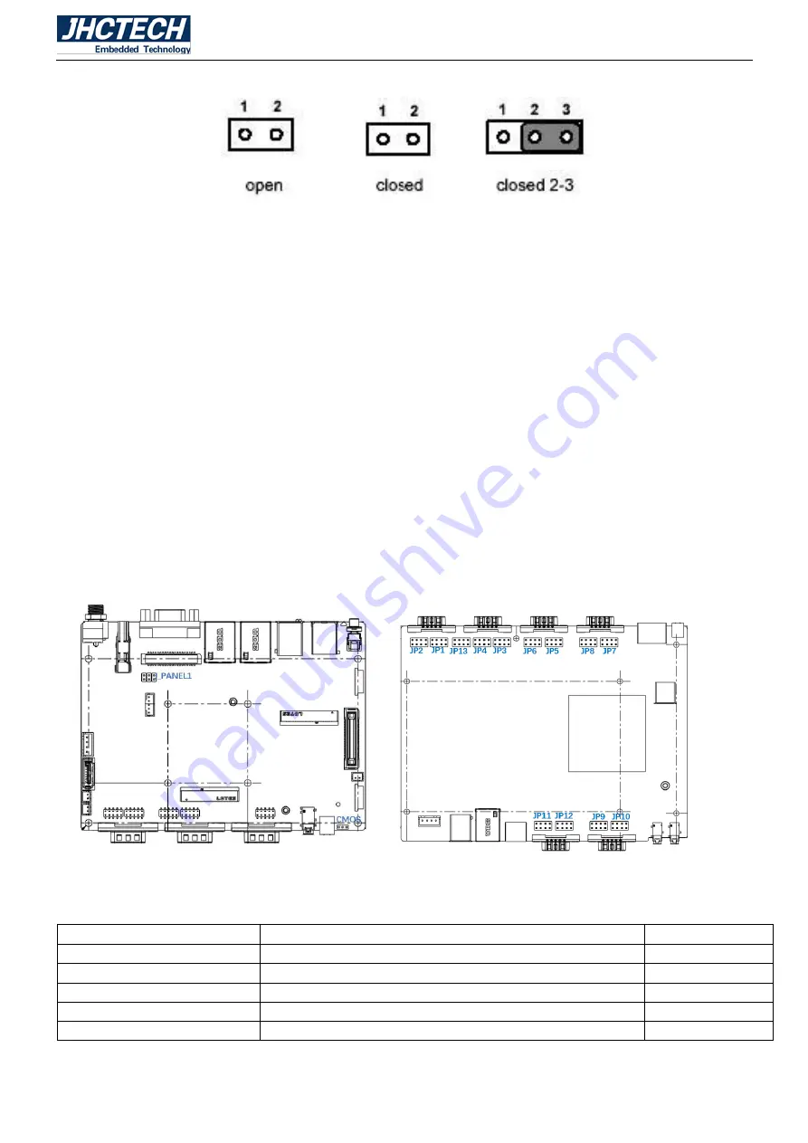
Figure 2.4
A pair of needle-nose pliers may be helpful when working with jumpers. If you have any doubts about the
best hardware configuration for your application, contact your local distributor or sales representative
before you make any changes.
Tip
: How to identify the first pin of the interface or jumper, observe the text mark next to the plug socket,
it will be indicated by "1" or bold lines or triangle symbols; look at the pad on the back, the square pad is
the Pin 1; all jumpers have a white arrow next to pin 1.
2.3 Jumper Location
The KMDA-2702 Embedded Box Computer has a number of jumpers inside the chassis that allows you
to configure your system to suit your application. The table below lists the functions of the various
jumpers. The table below shows the function of each of the board’s jumpers:
Figure 2.5
Jumpers
Jumper
Name
Description
CMOS
Clear CMOS Data Setting
3-Pin Block
J_PANEL1
LVDS screen 3.3V/5V/12V Power supply Select
6-Pin Block
JP1/JP3/JP5/JP7/JP9/JP11
COM5/6/7/8/9/10 RS232/RS485/RS422 Mode Select
8-Pin Block
JP2/JP4/JP6/JP8/JP10/JP12
COM5/6/7/8/9/10 Matching resistor Select
8-Pin Block
JP13
COM5/COM6 RI/5V/12V Power supply Select
8-Pin Block
Содержание KMDA-2702
Страница 1: ...User s Manual 1 User s Manual KMDA 2702 Ver A1 0 Date 15 October 2018 ...
Страница 2: ...User s Manual 2 Version Note No Ver Note Date Writer 1 A1 0 first publish 20180815 Tracy Liu ...
Страница 8: ...User s Manual 1 General Information CHAPTER 1 ...
Страница 12: ...User s Manual 5 Main board rear Figure 1 1 Sub board ECB 153 Figure 1 2 ...
Страница 13: ...User s Manual 6 Sub card ECD 7150 Figure 1 3 KMDA 2702 Dimensions Uint mm Figure 1 4 ...
Страница 14: ...User s Manual 7 Hardware Installation CHAPTER 2 ...
Страница 21: ...User s Manual 14 2 4 I O Button and LED indication Front view Figure 2 11 Rear view Figure 2 12 ...
Страница 31: ...User s Manual 24 Figure 2 28 Figure 2 29 Figure 2 30 ...
Страница 32: ...User s Manual 25 Figure 2 31 Figure 2 32 Figure 2 33 ...
Страница 33: ...User s Manual 26 Figure 2 34 Figure 2 35 Figure 2 36 ...
Страница 35: ...User s Manual 28 Figure 2 39 Figure 2 40 Figure 2 41 ...
Страница 36: ...User s Manual 29 Figure 2 42 Figure 2 43 Figure 2 44 ...
Страница 38: ...User s Manual 31 Figure 2 47 Figure 2 48 Figure 2 49 ...
Страница 39: ...User s Manual 32 Figure 2 50 Figure 2 51 Figure 2 52 ...
Страница 41: ...User s Manual 34 BIOS Setup CHAPTER 3 ...
Страница 61: ...User s Manual 54 Driver Installation CHAPTER 4 ...
Страница 67: ...User s Manual 60 SYSTEM RESOURCE CHAPTER 5 ...


