


13 Safe Standstill (Option)
JetWeb
106
Jetter AG
Bottom left, the "Safe Standstill" function has been illustrated. It consists of two
mainly identical, yet independent signal paths 1 and 2. Each path consists of a DC/
DC converter, which creates an output voltage of 5 Volt out of the connected input
voltage. Further, each converter is equipped with a status output, the data of which
are transmitted to the DSP. Out of this, the DSP recognizes immediately, whether the
corresponding input is active or deactivated, and it activates, respectively
deactivates the pulse outputs. The output voltage OUT1 leads to a driver-level, at
which it takes up the pulse patterns for the "upper" IGBTs and transmits them to the
opto isolators. The same way, the opto isolators themselves have been supplied with
this voltage. By analogy with opto isolators, the output voltage OUT2 supplies the
drivers of various levels and the opto isolators of the "lower" IGBTs.
This means that for driving the motor, both inputs Enable1 and Enable2 have to be
controlled. At calling up "Safe Standstill", the inputs have to be de-energized. This
way, supplying the driver-levels and opto isolators will not be necessary any more;
the same way, the DSP will recognize this at the status outputs. This causes the
motor to come to "Safe Standstill".
In a fault condition, it is sufficient to only deactivate only one path, as a phase
sequence is not generated any more, if only the "upper" or only the "lower" IGBTs
have been switched off.
For decoupling the control signals of the DSP, especially for excluding a faulty supply
of the driver levels / opto isolator by the control signals of the DSP, all signals have
been equipped with resistors of apt design and values at their interface.
The broken line marks the border between the safety-relevant components.
Fig. 30: Possible rotation angle in case of defective IGBTs
In the risk analysis, this behavior has to be taken into consideration. If this can lead
to a hazard, the function is not apt for use in this case.
Yet, the possibility that this occurs is very low. If the unit for the failure rate of an IGBT
is 100 fit (10E-7 per hour), the possibility of two IGBTs failing at the same time is
10E-14 per hour (several million years). Out of these, only 6 out of 15 cases lead to
jerking. This means that practically, there is no possibility of this to happen.
Moreover, the IGBTs are continually being checked at each commutation.
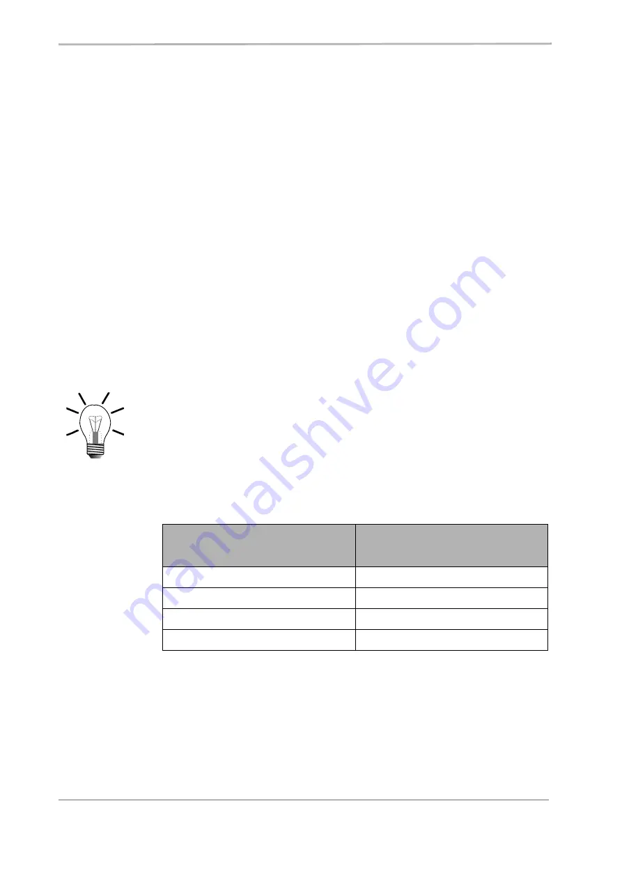
Note!
In spite of these safety precautions, the motor can jerk due to defective IGBTs.
The possible rotation angle depends on the pole pair number of the motion
system in use.
Pole Pair Number of the
Motor
Possible Rotation Angle
1
180°
2
90°
3
60°
5
36°
Содержание JetMove 225-480
Страница 1: ...JetMove 225 480 Digital Servo Amplifier 60874967...
Страница 10: ...Table of Contents JetWeb 10 Jetter AG Appendix D Index of Illustrations 123 Appendix E Index 124...
Страница 24: ...1 Safety Instructions JetWeb 24 Jetter AG...
Страница 36: ...4 Mounting Dimensions JetWeb 36 Jetter AG...
Страница 44: ...5 Technical Data JetWeb 44 Jetter AG...
Страница 45: ...JetMove 225 480 Jetter AG 45 6 Drive Controller Structure Fig 7 Block diagram of drive controller structure...
Страница 76: ...7 Description of Connections JetWeb 76 Jetter AG...
Страница 84: ...JetWeb 84 Jetter AG...
Страница 88: ...JetWeb 88 Jetter AG...
Страница 116: ...15 Ordering Information JetWeb 116 Jetter AG...
Страница 117: ...JetMove 225 480 Appendix Jetter AG 117 Appendices...
Страница 118: ...Appendices JetWeb 118 Jetter AG...
Страница 119: ...JetMove 225 480 Appendix Jetter AG 119 Appendix Appendix A Recent Revisions Style and spelling have been revised...


