PAGE 22 of 54
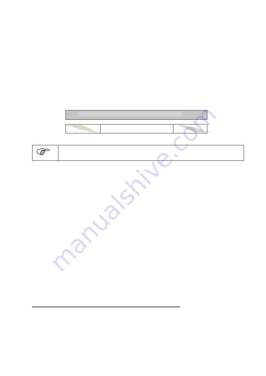
If you look at the following servo travel graph below, you can see how the ECU detects a failsafe condition.
The gray bar is the transmitters throttle channel end points set for +/- 100% travel. This is the travel range
when setting
the transmitter’s failsafe. The white bar is a reduced end point travel set for +/- 50% travel.
This is the value that will be taught into the ECU. If the throttle input to the ECU is between 50% for low
throttle, low throttle trim and 50% for high throttle, then this would be within the
ECU’s taught range and will
operate normall
y. If a failsafe condition exists, the transmitter’s pre-programmed 100% low throttle, low
throttle trim will be outputted by the receiver and this value would be outside of the ECU’s taught in range.
The ECU will now automatically set the turbine to idle (after a default 0.1 second
FailSafe delay
) and start
a programmable timer. The timer is set to 2 seconds by default. If the timer times out, the ECU will shut-off
the turbine. If at any time during this countdown the receivers signal is reacquired, the ECU timer will be
reset and the turbine will go back to the speed the throttle stick is currently at.
Setting the travel range to +/- 50% does not affect the RPM range of the turbine.
Low Throttle
High Throttle
FOR TWO CHANNEL OPERATION:
Do not enable the auxiliary channel in your transmitter for failsafe.
Keep it in
hold mode
only. The auxiliary channel is always designed to stop the turbine instantly if
commanded to do so.
For spread spectrum radios, there are two different ways to set the failsafe. It is either accomplished by the
transmitter
’s failsafe menu or by binding the receiver to the transmitter. Refer to your transmitter’s manual
on how to set the failsafe.
To set the failsafe, you must execute the following steps. It is
VITAL
that these steps be performed in this
order for the failsafe feature to operate properly.
YOU MUST PERFORM THESE STEPS!
Inspect the transmitter programming to ensure that dual rates and exponential functions are
disabled and sub trim is set at zero for both throttle and, if two channel operation, the auxiliary
channel. Some transmitters have a travel limit menu in addition to travel end points menu. If so, set
the limits to its maximum amount >= 100%
Set your transmitters end point travel parameter to +/- 100% for low and high throttle.
If you are using two channel operation, position the auxiliary channel to the center position.
Set your transmitters throttle stick to low throttle and low throttle trim. Depending on the radio
system you are using, either set the throttle channel for failsafe and store/memorize this minimum
position or bind your receiver to the transmitter.
Return to the travel end point menu and now set the low and high throttle end point to +/- 50%.
Now you must teach in these values into the ECU. Refer to
Learn R/C
section next in this manual.
Additional Failsafe menus are explained in the manual’s advanced section.
If you change your transmitter’s failsafe after these steps are completed, you must redo the
following instructions again
.
Before setting failsafe, set throttle travel at 100% low / 100% high throttle
Teach ECU at 50% low / 50% high
throttle
Set Failsafe
Failsafe area
Failsafe area
Содержание RX Series
Страница 15: ...PAGE 15 of 54 Complete System Connection Diagram RXi...
Страница 16: ...PAGE 16 of 54 System Connection RXi Photo To fueltank To receiver...
Страница 29: ...PAGE 29 of 54 Flashing E EGT sensor defective Last Off Condition Low RPM shut off from previous run...
Страница 38: ...PAGE 38 of 54 Connection Diagram of the Smoke System...


