background image

 14

4.  Select proper speed and feed rate for material 

being cut.  

5.  Material to be cut must be securely held in vise. 

6.  Check to see that coolant level is adequate and 

turn on coolant pump if material to be cut 
requires it. Machine should be filled with 
approximately 15 L (4 gal.) of proper coolant 
mixture. Follow directions on product maker’s 
label and fill coolant tank through chip tray area. 

7.  Do not start cut on a sharp edge. 

8.  Keep machine lubricated. See 

sect. 10.2.


9.4

  General operating procedure 


All blade covers and guards 

must be in place and secured before turning on 
band saw.


1.  Select proper speed for type of material to be 

cut. 

2.  Close feed rate knob and lift bow high enough 

to clear workpiece. 

 Make sure blade is not in 

contact with workpiece when motor is 
started. Do not drop bow onto workpiece or 
force blade through workpiece. 

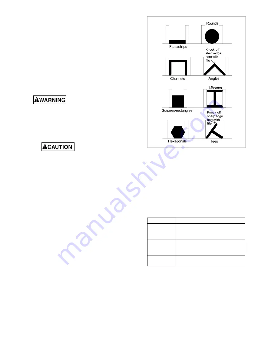
3.  Place stock between vise jaws, set stock for 

desired width of cut and tighten vise. (See 
Figure 9-3 for recommended placement in vise 
of varied workpiece shapes.) 

4.  Make sure left blade guide bracket is adjusted 

as close as possible to left vise jaw. 

5.  Start motor and allow machine to reach 

operating speed.  

6.  Adjust coolant valves as desired. 

7.  Turn feed rate control knob for desired rate. 

Allow blade to slowly enter workpiece. 

8. 

Saw will shut off at completion of cut.


9.5

  Evaluating cutting efficiency 

Is the blade cutting efficiently? The best way to 
determine this is to observe the chips formed by the 
cutting blade:  

If chip formation is powdery, then feed rate is much 
too light, or blade is dull.  

If chips formed are curled, but colored — that is, 
either blue or straw-colored from heat generated 
during the cut — then feed rate is too high.  

If chips are slightly curled and are not colored by 
heat — blade is sufficiently sharp and is cutting at 
its most efficient rate. 


Figure 9-3 

9.6

  Blade selection 

The saw is provided with a blade that is adequate 
for a variety of cut-off jobs on a variety of common 
materials.  

See Table 3 for recommended speeds for various 
materials. These selections, while appropriate for 
many shop cutting needs, do not encompass the 
wide variety of blades of special configuration (tooth 
pitch and set) and special alloys for cutting unusual 
or exotic materials.  

Speed/FPM Material 

100 

Tool Steel, Stainless Steel, 
Phosphor Bronze, Hard Bronze, 
Hard Cast Iron, Malleable Iron 

165 

Mild Steel, Soft Cast Iron,  
Med. Hard Brass,  
Med.Hard Bronze 

230 

Soft Brasses and Bronzes,  
Hard Aluminum, Plastics 

Table 3 

A coarse blade could be used for a solid steel bar 
but a finer tooth blade would be used on a thin-wall 
tube. In general, the blade choice is determined by 
the thickness of the material; the thinner the 
material, the finer the tooth pitch.  

A minimum of three teeth should be on the work 
piece at all times for proper cutting. The blade and 
workpiece can be damaged if the teeth are so far 
apart that they straddle the workpiece.  


Содержание MBS-1018-1

Страница 1: ...ons and Parts Manual Horizontal Dual Mitering Band Saw Models MBS 1018 1 MBS 1018 3 JET 427 New Sanford Road LaVergne Tennessee 37086 Part No M 413410 Ph 800 274 6848 Edition 2 06 2017 www jettools co...

Страница 2: ...or maintenance with the machine unplugged from the power source 14 Remove adjusting keys and wrenches Form a habit of checking to see that keys and adjusting wrenches are removed from the machine bef...

Страница 3: ...mmed pieces until blade has stopped 36 Don t use in dangerous environment Don t use power tools in damp or wet location or expose them to rain Keep work area well lighted 37 Use proper extension cord...

Страница 4: ...2 Auxiliary coolant hose 13 9 3 Prior to Operation 13 9 4 General operating procedure 14 9 5 Evaluating cutting efficiency 14 9 6 Blade selection 14 9 7 Blade break in procedures 15 10 0 User maintena...

Страница 5: ...omments please contact your local supplier or JET JET can also be reached at our web site www jettools com Retain this manual for future reference If the machine transfers ownership the manual should...

Страница 6: ...s 50 125 200 275 SFPM 50 125 200 275 SFPM Coolant tank capacity 15 L 4 gal 15 L 4 gal Gearbox oil capacity 850 mL 0 9 qt 850 mL 0 9 qt 90 degrees 60 degrees 45 degrees Tubing Round 10 in 254mm 6 in 15...

Страница 7: ...levels and are not necessarily to be seen as safe operating levels As workplace conditions vary this information is intended to allow the user to make a better estimation of the hazards and risks invo...

Страница 8: ...bolts with hex nuts through the base flanges as shown in sect 12 2 1 index 280 and 283 4 Place a level on the table surface and check side to side and front to back 5 Adjust leveling screws until mach...

Страница 9: ...circuit the reconnection should be made by qualified service personnel and after reconnection the tool should comply with all local codes and ordinances If hardwired Permanently connected tools This t...

Страница 10: ...e blade guide brackets F Figure 7 1 must be set to just clear the workpiece but should not interfere with workpiece or other saw components during bow s descent Loosen knobs and slide brackets into po...

Страница 11: ...e away from wheel shoulder then immediately turn single hex adjustment screw in opposite direction so that blade stops then moves slowly toward shoulder Keep fingers clear of blade and wheel to avoid...

Страница 12: ...components then tighten both handles T Figure 7 6 vise adjustment 7 7 Bow swivel adjustment Refer to Figures 7 7 and 7 8 1 Remove 90 stop pin V 2 Lift up on lever W and push bow to desired angle accor...

Страница 13: ...ntrol F Sets amount of downward force that is applied to saw blade The feed rate is proportional to opening of valve Increasing valve opening counterclockwise increases feed rate decreasing valve open...

Страница 14: ...ency Is the blade cutting efficiently The best way to determine this is to observe the chips formed by the cutting blade If chip formation is powdery then feed rate is much too light or blade is dull...

Страница 15: ...and debris Keep slide areas such as vise ways and T slot slide for bow swiveling and behind scale where blade brackets slide clean and oiled Make sure vise lead screw remains free of cuttings or other...

Страница 16: ...ease spring tension Hard spots in workpiece or scale on in workpiece Increase feed pressure hard spots Reduce speed increase feed pressure scale Work hardening of material especially stainless steel I...

Страница 17: ...de too coarse for workpiece especially with tubular stock Use blade with fine tooth pitch Blade too fine for workpiece especially with heavier soft material Use blade with coarse tooth pitch Insuffici...

Страница 18: ...18 12 1 1 MBS 1018 1 MBS 1018 3 Bow Assembly Exploded View...

Страница 19: ...6 Special Washer 1 28 MBS 1018 1 28 Wheel LH 1 29 BB 6306ZZ Bearing 6306ZZ 2 MBS 1018 GBA Gear Box Assembly includes 31 47 50 58 82 1 31 EHB916V 31 Output Shaft 1 32 EHB916V 32 Oil Seal 32 42 7 1 33 B...

Страница 20: ...95MFC Motor Fan Cover 1 EHB1018V 95MF Motor Fan 1 EHB1018V 95MJB Motor Junction Box 1 EHB1018VM 95 Motor 2HP 230 460V 3PH 1 EHB1018VM 95MFC Motor Fan Cover 1 EHB1018VM 95MF Motor Fan 1 EHB1018VM 95MJB...

Страница 21: ...3 16 x 3 8 2 154 2 F002633 Flat Washer 3 16 2 155 MBS 1018 1 155 Bracket LH 4 156 EHB916V 156 Blade Cover 1 156 1 EHB916V 156 1 Screw 3 16 x 3 8 2 156 2 F002633 Flat Washer 3 16 2 157 MBS1018 1 157 B...

Страница 22: ...22 12 2 1 MBS 1018 1 MBS 1018 3 Base Assembly Exploded View...

Страница 23: ...216 EHB916V 216 Seal 1 217 EHB916V 217 O Ring 1 218 TS 0561021 Hex Nut 5 16 x18T 2 219 EHB916V 219 Tube Assembly 1 221 EHB916V 221 Tube Fitting 1 222 EHB916V 222 Tube Fitting 1 223 EHB916V 223 Ext Ret...

Страница 24: ...rface 1 273 TS 0267071 Socket Set Screw 1 4 20 3 4 6 274 TS 0051051 Hex Cap Screw 5 16 18 1 3 276 MBS 1018 1 276 Seat 1 277 EHB1018VM 277 Movable Block 1 278 EHB916V 278 Spray Gun Set 1 278 1 EHB916V...

Страница 25: ...8061 Socket Head Cap Screw 5 16 18 1 2 314 EHB1018VM 314 Fixing Rod For Spring 1 315 TS 0211071 Socket Head Cap Screw 1 2 1 1 2 1 316 EHB1018VM 316 Spring 1 317 EHB1018VM 317 Spring Cover 1 318 EHB101...

Страница 26: ...26 12 3 1 MBS 1018 1 MBS 1018 3 Electrical Box Assembly Exploded View...

Страница 27: ...otor Cable 1 308 16 MBS1018 1 308 16 Pump Cable 1 308 19 MBS1018 1 308 19 Limit Switch Cable 1 12 3 3 MBS 1018 3 Electrical Box Assembly Parts List Index No Part No Description Size Qty 308 1 EHB1018V...

Страница 28: ...8 13 0 Electrical Connections 13 1 Wiring Diagram for MBS 1018 1 K1 K2 contactor LS4 limit switch M1 main motor M2 coolant pump OL1 overload PB1 emergency stop button PB2 PB3 pushbutton TR transformer...

Страница 29: ...29 13 2 Wiring Diagram for MBS 1018 3...

Страница 30: ...tional action needed JET has Authorized Service Centers located throughout the United States For the name of an Authorized Service Center in your area call 1 800 274 6846 or use the Service Center Loc...

Страница 31: ...31 This page intentionally left blank...

Страница 32: ...32 427 New Sanford Road LaVergne Tennessee 37086 Phone 800 274 6848 www jettools com...

Отзывы: