


12
8.0
Coolant preparation
Follow coolant manufac-
turer’s recommendations for use, care and
disposal.
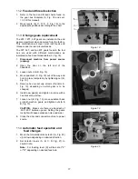
1. Remove rear access cover on tailstock end.
Make sure coolant tank has not shifted during
transport and is located properly under the
recovery chute (Fig. 10).
2. Pour three gallons of coolant mix into drip pan.
3. After machine has been connected to power,
turn on coolant pump and check to see coolant
is cycling properly.
4. Fasten coolant door to stand.
9.0
Electrical connections
Electrical connections must be
made by a qualified electrician in compliance
with all relevant codes. This machine must be
properly grounded to help prevent electrical
shock and possible fatal injury.
The
GH-1440-1
lathe is rated at
3HP, single-
phase, 230V only.
The
GH-1440-3
lathe is rated
at
3HP, 3-phase, 230V/460V (prewired 230V).
Confirm power available at the lathe's location is
the same rating as the lathe.
Lathe Power Source Junction Box:
Remove the
cover. Run the main power through the strain relief
bushing and attach the ground, followed by power
leads. Replace the cover.
Main Power Switch:
Located on the backside of
the machine. Turns the power to the machine on
and off.
Make sure the lathe is properly grounded.
Power is connected properly when pulling up on
the forward-reverse lever causes spindle to rotate
counterclockwise as viewed from tailstock. If the
chuck rotates in clockwise direction, disconnect
lathe from power source, switch two of three power
leads, and re-connect lathe to power source.
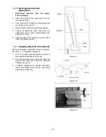
9.1
Voltage conversion (GH-1440-3
only)
Disconnect machine from
power source. Failure to comply may cause
serious injury!
To switch from 230- to 460-volt operation:
Figure 10
Main Motor:
Change the wires according to the
diagram on inside of motor junction box.
Transformer:
Remove electrical panel on rear of
machine, headstock side, and switch wire from 230V
terminal to 460V terminal as outlined on the
transformer.
Coolant Pump:
Open access panel on base at
tailstock end. Change wires in coolant pump junction
box according to diagram on inside of junction box
cover.
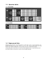
Содержание GH-1440
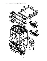
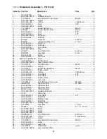
Страница 23: ...23 14 1 1 Headstock Assembly I Exploded View ...
Страница 26: ...26 14 2 1 Headstock Assembly II Exploded View ...
Страница 28: ...28 14 3 1 Headstock Assembly III Exploded View ...
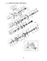
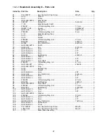
Страница 30: ...30 14 4 1 Gearbox Assembly I Exploded View ...
Страница 33: ...33 14 5 1 Gearbox Assembly II Exploded View D C B ...
Страница 36: ...36 14 6 1 Apron Assembly I Exploded View ...
Страница 38: ...38 14 7 1 Apron Assembly II Exploded View A D E C B A B C D E ...
Страница 40: ...40 14 8 1 Saddle and Cross Slide Assembly Exploded View ...
Страница 43: ...43 14 9 1 Top Slide and Tool Post Exploded View ...
Страница 45: ...45 14 10 1 Tailstock Assembly Exploded View ...
Страница 47: ...47 14 11 1 Bed and Shaft Assembly Exploded View ...
Страница 50: ...50 14 12 1 Stand and Brake Assembly Exploded View ...
Страница 52: ...52 14 13 1 End Gear Assembly Exploded View ...
Страница 56: ...56 14 16 1 Steady Rest Parts List ...
Страница 61: ...61 14 20 1 Accessories I Exploded View ...
Страница 65: ...65 15 0 Electrical Connections 15 1 Wiring Diagram 1 Phase ...
Страница 66: ...66 15 2 Wiring Diagram 3 Phase ...
Страница 68: ...68 427 New Sanford Road LaVergne Tennessee 37086 Phone 800 274 6848 www jettools com ...


