


20
12.7
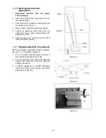
Headstock alignment
The headstock has been aligned at the factory and
should not require adjustment. However, if
adjustment is deemed necessary, follow the
procedure below to align the headstock:
1. Using a machinist's precision level on the
bedways, make sure the lathe is level side to
side and front to back. If the lathe is not level,
correct to a level condition before proceeding.
Re-test alignment if any leveling adjustments
were made.
2. From steel bar stock of approximately two
inches in diameter, cut a piece approximately
eight inches long.
3. Place two inches of bar stock into chuck and
tighten chuck. Do not use the tailstock or
center to support the other end.
4. Set up and cut along five inches of bar stock.
5. Using a micrometer, measure the bar stock
next to the chuck and at the end. The
measurement should be the same.
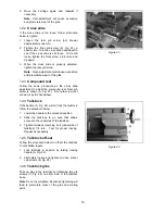
6. If the measurements are not the same and
adjustment is required, loosen hex socket cap
screws (A, Fig. 25) which hold the headstock
to the bed.
Do not
loosen completely; some
drag should remain.
7. Adjust two screw nuts (B, Fig. 25) located on
the endgear side of the headstock. Loosen
one and tighten the other. Make another cut.
Keep adjusting screw nuts after each cut until
the bar stock measurements are the same.
Tighten all headstock screws.
12.8
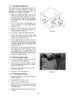
Removing gap bridge
1. To remove gap bridge, locate two nuts (A, Fig.
26) in the center of the gap bridge.
2. Using an open end wrench, tighten the two
nuts. This will cause the taper pins to release.
Remove the taper pins.
3. Remove six hex socket cap screws (B, Fig.
26) with a hex wrench.
4. Gap bridge can now be removed.
12.9
Installing gap bridge
1. Clean the bottom and the ends of the gap
bridge thoroughly.
2. Set gap bridge in place and align.
3. Remove nuts from the taper pins.
4. Slide taper pins in their respective holes and
seat using a mallet. Install nuts on the taper
pins finger tight.
5. Install six socket head cap screws and tighten
securely.
Figure 25
Figure 26
Содержание GH-1440
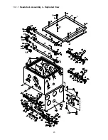
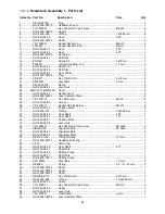
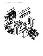
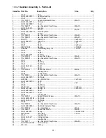
Страница 23: ...23 14 1 1 Headstock Assembly I Exploded View ...
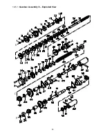
Страница 26: ...26 14 2 1 Headstock Assembly II Exploded View ...
Страница 28: ...28 14 3 1 Headstock Assembly III Exploded View ...
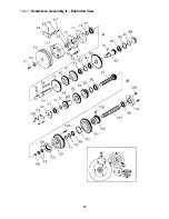
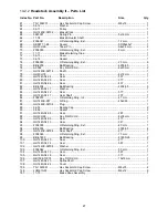
Страница 30: ...30 14 4 1 Gearbox Assembly I Exploded View ...
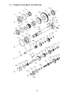
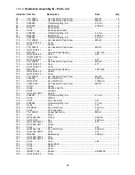
Страница 33: ...33 14 5 1 Gearbox Assembly II Exploded View D C B ...
Страница 36: ...36 14 6 1 Apron Assembly I Exploded View ...
Страница 38: ...38 14 7 1 Apron Assembly II Exploded View A D E C B A B C D E ...
Страница 40: ...40 14 8 1 Saddle and Cross Slide Assembly Exploded View ...
Страница 43: ...43 14 9 1 Top Slide and Tool Post Exploded View ...
Страница 45: ...45 14 10 1 Tailstock Assembly Exploded View ...
Страница 47: ...47 14 11 1 Bed and Shaft Assembly Exploded View ...
Страница 50: ...50 14 12 1 Stand and Brake Assembly Exploded View ...
Страница 52: ...52 14 13 1 End Gear Assembly Exploded View ...
Страница 56: ...56 14 16 1 Steady Rest Parts List ...
Страница 61: ...61 14 20 1 Accessories I Exploded View ...
Страница 65: ...65 15 0 Electrical Connections 15 1 Wiring Diagram 1 Phase ...
Страница 66: ...66 15 2 Wiring Diagram 3 Phase ...
Страница 68: ...68 427 New Sanford Road LaVergne Tennessee 37086 Phone 800 274 6848 www jettools com ...


