16
MILL
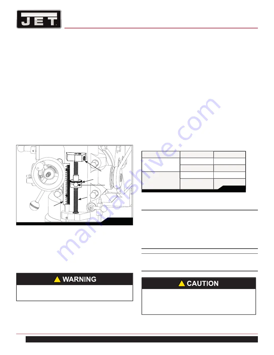
9.14 DEPTH SCALE AND STOP
Referring to Figure 14:
The Depth Scale and Stop are used in drilling operations
to set the depth of the drilled hole. The depth scale is
located on the front of the mill head. The scale consists of
a Micrometer Adjusting Nut (A), Micro-nut quick adjust (B),
Quill Stop (C), Quill Stop Screw (D), and Scale (E).
The Micrometer Adjusting Nut is set to the desired di-
mension and is held in place by the friction applied by the
micro-nut quick adjust. The quill stop provides a positive
stop for quill travel.
The graduations on the micrometer nut are in 0.001 inch
increments. Adjustment of quill travel is made by rotat-
ing the micrometer nut, or by pressing the micronut quick
adjust button and sliding the nut up or down.
9.15 POWER FEED OPERATION
The Feed Trip Adjustment sets the point at which the quill
will reset during Power Feed.
Referring to Figure 15:
1. Move adjuster nut to allow for ample spindle travel.
2. With the Quill Feed Handle (J), advance the quill to
the point where the feed should stop.
3. Engage the Feed Trip Cam Lever (D) by pulling away
from head assembly.
4. Adjust Micrometer Adjusting Nut (H) against Quill Stop
(G).
5. Continue turning the Micrometer Adjusting Nut (H)
until the Feed Trip Cam Lever (D) trips.
6. Ensure Quill Lock (K) is disengaged by rotating count-
erclockwise.
7. Start the spindle (See Fig. 5):
8. Select feed rate with the Variable Speed Control
Handwheel
(E).
9. Set the Feed Rate Lever (B) to the feed rate required
for the tooling and material required.
10. Place the Quill Feed Engagement Lever (F) in the
Engaged
position.
11. Select feed direction by setting the Feed Direction
Knob (C) position per the table:
Spindle Direction
Feed Direction
Knob Position
CW
Down
In
Up
Out
CCW
Down
Out
Up
In
12. Engage the Feed Trip Cam Lever (D) by pulling away
from head assembly.
Note: Due to variables in tool diameter, coatings,
coolant, and materials, no specific spindle speed or
feed rate recommendations are provided. Use general
shop manuals that have data applicable to the milling
and drilling operations being performed. Or, contact
the supplier of the tooling, coolant, and material for
specific recommendations.
IMPORTANT: The power feed can be used for drills up
to 3/8” in diameter (mild steel). Use manual feed for
drills larger than 3/8”.
Be sure that the Manual Fine Feed Handwheel is re-
moved. Failure to comply may cause serious injury.
!
The overload clutch is factory set to hold up to 200
lbs. downfeed pressure on the quill (accommodates
drills up to 3/8”). Do not attempt to adjust clutch
pressure.
!
Table 2
Fig. 14
E
D
A
C
B
Содержание ETM-949
Страница 9: ...9 ETM 949 ETM 949EVS Fig 2 ETM 949 DIMENSIONS ...
Страница 12: ...12 MILL Fig 5 Fig 4 Motor Switch ...
Страница 25: ...25 ETM 949 ETM 949EVS TABLE ASSEMBLY ETM 949 ETM 949EVS ...
Страница 48: ...48 MILL 14 0 WIRING DIAGRAM ETM 949 ...
Страница 49: ...49 ETM 949 ETM 949EVS WIRING DIAGRAM ETM 949EVS E type inverter ...
Страница 50: ...50 MILL WIRING DIAGRAM ETM 949EVS B type inverter ...
Страница 51: ...51 ETM 949 ETM 949EVS NOTES ...
Страница 52: ...52 MILL NOTES ...


