7
EHB-1018VM | EHB-1018VMH
6.0 UNCRATING AND ASSEMBLY
Note: Read and understand the entire manual before
attempting setup or operation.
1. Finish uncrating the saw and inspect for damage.
Should any have occurred, contact your local distribu-
tor.
2. Remove all bolts attaching machine to shipping base.
3. Leave packing material between vise clamps and saw
head intact until band saw has been lifted to its fi nal
position.
4. Clean all rust protected surfaces with kerosene or
diesel oil to remove protective coating. Do not use
gasoline, paint thinner, mineral spirits, etc. These may
damage painted surfaces.
5. Lubricate all slideways with SAE 10W oil.
7.0 INSTALLATION
For best performance, the band saw should be located on
a solid and level foundation. Allow room for servicing and
for moving large stock around the band saw when decid-
ing a location for the machine.
1. Using lifting straps that are isolated from the band
saw’s
fi nished surfaces, lift machine and place in
desired location. See Figure 1 for strap placement.
2. Install four leveling bolts with lock nuts on both sides
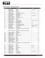
of the base as shown in the parts breakdown on page
16, items 2 and 3.
3. Place a level on the table surface and check side-to-
side and front-to-back.
4. Adjust leveling screws until machine is level in both
directions and tighten locking nuts.
8.0 ELECTRICAL CONNECTIONS
The EHB-1018VM/VMH is rated at 230/460V, 3 phase.
Confi rm that power available at the saw’s location match-
es that for which the saw is wired.
If the saw runs backward, disconnect from power and
switch any two of the three power leads.
Fig. 1
9.0 CONTROLS
Refer to Figure 2.
Power Indicator Light (A)
– lit whenever machine is
running.
Start Button (B)
– press to start band saw.
Stop Button (C)
– press to stop band saw.
Emergency Stop Button (D)
– press to immediately stop
all machine functions.
Blade Up Button (E)
– when in automatic mode, press to
raise saw head.
Blade Down Button (F)
– when in Automatic mode, press
to lower saw head.
Coolant Switch (G)
– Turn arrow to “I” to turn on coolant
fl ow. Turn arrow to “O” to stop coolant fl ow.
Manual/Auto Switch (H)
– due to saw head weight, use
the auto mode to raise and lower saw head.
Hydraulic Vise Closed Button (I)
– press to close vise.
Hydraulic Vise Open Button (J)
– press to open vise.
Saw Head Down Feed Speed Control (K)
– this knob is
used to set the amount of downward force that is applied
to the saw blade. The feed rate is proportional to the
opening of the valve. When set to zero, the saw head is
locked in the raised position. Increasing the valve opening
(counterclockwise adjustment) increases the feed rate;
decreasing the valve opening (clockwise adjustment)
reduces the feed rate.
!
All electrical connections must be done by a
qualifi ed electrician. All adjustments or repairs must
be done with machine disconnected from power
source. Failure to comply may cause serious injury.
Содержание Elite EHB-1018VM
Страница 15: ...15 EHB 1018VM EHB 1018VMH SAW STAND AND BED ASSEMBLY EHB 1018VM 1018VMH...
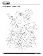
Страница 20: ...20 Horizontal Band Saw SAW ARM ASSEMBLY EHB 1018VM 1018VMH...
Страница 29: ...29 EHB 1018VM EHB 1018VMH NOTES...
Страница 30: ...30 Horizontal Band Saw NOTES...
Страница 31: ...31 EHB 1018VM EHB 1018VMH NOTES...
Страница 32: ...32 Horizontal Band Saw NOTES...


