background image

9

EHB-1018VM | EHB-1018VMH

9.    Put light tension on the blade and work it on both  


  wheels, as shown in Fig. 5. 

  MAKE SURE THAT THE BACK OF THE BLADE  

IS AGAINST THE WHEEL FLANGES OF  


BOTH WHEELS. THIS IS VERY IMPORTANT.

10.  When you are sure the back of the blade is against    

 the wheel fl anges of both wheels and properly insert- 
  ed into the guides, fi nish putting tension on the blade.

11.  Jog the power “on” and “off” to be sure the blade is in  

  place and tracking properly.  
  If blade is not tracking properly refer to the section    
  “

Tracking the Blade”. 

Fig. 5

Fig. 4

F

D

E

12.2  ADJUSTING BLADE GUIDE BRACKETS

The blade guides should be set as close to the vise jaw as 
possible. The right blade guide bracket (A) Fig. 6, is not 
adjustable and is set at the factory to clear the right hand 
vise jaw.  The left blade guide bracket (B) can be moved 
to the left or right depending on the position of the left 
hand vise jaw (C).  
To move the left blade guide bracket (B), loosen hand 
knob (D), position blade guide bracket (B) and tighten 

hand knob (D).

Fig. 6

A

B

C

D

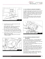
12.3   ADJUSTING BLADE GUIDE ROLLER 

BEARINGS

The back of the blade (A) Fig. 7, should ride against the 
back-up support bearing (B) which is positioned at an 
angle so as to provide greater bearing support, eliminating 

bearing wear and extending blade life.

The saw blade (A) should also ride between the two roller 
bearings (C) and (D) Fig. 7. 

The rear bearing (C) on the left hand blade guide can be 
easily adjusted to suit blade thickness by loosening nut 
(E).  The bearing (C) is on an eccentric which enables it to 
be adjusted for blade thickness in the same manner with 
the exception that the adjustable roller bearing is in the 
forward position.

Part (F) shown Fig. 8 is a tungsten carbide block, after 
completing the adjustments shown in Fig. 7, tighten the 
Part (F) onto the surface of the saw blade.

Содержание Elite EHB-1018VM

Страница 1: ...tructions and Parts Manual Horizontal Band Saw Models EHB 1018VM EHB 1018VMH JET 427 New Sanford Road LaVergne Tennessee 37086 www jettools com Ph 855 336 4032 Part No M 891070 REV C2 09 2018 Copyrigh...

Страница 2: ...y defects in workmanship or materials subject to the limitations stated below This warranty does not cover failures due directly or indirectly to misuse abuse negligence or accidents normal wear and t...

Страница 3: ...E FOR DEATH INJURIES TO PERSONS OR PROPERTY OR FOR INCIDENTAL CONTINGENT SPECIAL OR CONSEQUENTIAL DAMAGES ARISING FROM THE USE OF OUR PRODUCTS SOME STATES DO NOT ALLOW THE EXCLUSION OR LIMITATION OF I...

Страница 4: ...p past the elbows Remove all loose clothing and confine long hair Non slip footwear or anti skid floor strips are recommended Do not wear gloves 8 Wear ear protectors plugs or muffs during extended pe...

Страница 5: ...times so that you do not fall or lean against the blade or other moving parts Do not overreach or use excessive force to perform any machine operation 25 Use the right tool at the correct speed and f...

Страница 6: ...ications in this manual were current at time of publication but because of our policy of continuous improvement JET reserves the right to change specifications at any time and without prior notice wit...

Страница 7: ...8 0 ELECTRICAL CONNECTIONS The EHB 1018VM VMH is rated at 230 460V 3 phase Confirm that power available at the saw s location match es that for which the saw is wired If the saw runs backward disconne...

Страница 8: ...er s label and fill the coolant tank through the chip tray area 9 Do not start cut on a sharp edge 10 Keep machine lubricated See Lubrication section 12 0 OPERATING CONTROLS AND ADJUSTMENTS 12 1 REMOV...

Страница 9: ...t B can be moved to the left or right depending on the position of the left hand vise jaw C To move the left blade guide bracket B loosen hand knob D position blade guide bracket B and tighten hand kn...

Страница 10: ...ve the right hand vise jaw D to the left until the workpiece and right hand vise jaw clears the right hand guide arm 12 5 1 HYDRAULIC VISE The 1018VMH is equipped with a hydraulic vise This feature al...

Страница 11: ...wer source 12 7 ADJUSTING STOCK ADVANCE STOP The Stock Advance Stop is used mainly when more than one piece is to be cut to the same length Simply position the stop block A Fig 11 the desired distance...

Страница 12: ...which are wired into the electrical system are controlled by the start stop buttons The machine will automatically shut off when the cut is completed The lever A Fig 13 for the automatic shut off con...

Страница 13: ...e the 90 deg pin A Fig 19 to allow the frame to swing Set the indicator B Fig 19 to the desired angle on the scale C Fig 19 After the proper angle has been set push the lever down to hold the saw in p...

Страница 14: ...ont of gear case under right wheel cover Remove drain plug with a hex wrench 3 Replace drain plug 4 Remove filler cap A Figure 12 and fill gear box with Mobil DTE Oil Heavy Medium until level reaches...

Страница 15: ...15 EHB 1018VM EHB 1018VMH SAW STAND AND BED ASSEMBLY EHB 1018VM 1018VMH...

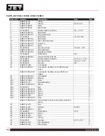
Страница 16: ...8 1 1 4 4 19 TS 0060081 Hex Cap Screw 3 8 16 1 3 4 1 20 TS 0561031 Hex Nut 3 8 1 21 EHB916V 206 Limit Switch 1 22 EHB1018VM 207 Limit Switch Seat Ser No 13080024 and lower 1 EHB1018VM 207N Limit Switc...

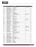
Страница 17: ...Wheel 1 55 1 EHB916V 249 1 Handle 1 56 EHB1018VM 250 Seat 1018VM only 1 56 1 TS 0051051 Hex Cap Screw 1018VM only 5 16 18 1 2 56 2 TS 0720081 Lock Washer 1018VM only 5 16 2 57 EHB1018VM 252 Acme Scre...

Страница 18: ...Coolant Pump 1 85 2 EHB916V 281 2 Pan Head Machine Screw 4 85 3 EHB916V 96 3 Way Coolant Block 1 85 4 EHB916V 281 4 Lock W Key 1 85 5 EHB916V 281 5 Lock W o Key 2 86 EHB1018VM 282 Bracket 1 87 TS 0070...

Страница 19: ...8VM 319 1 Open Pin 1 8 x1 2 121 EHB1018VMH 320 Hydraulic Vise Assembly includes 121 1 121 5 1018VMH only 1 121 1 EHB1018VMH 320 1 O Ring 40 46 2 121 2 EHB1018VMH 320 2 Oil Scraping Ring UHS70 2 121 3...

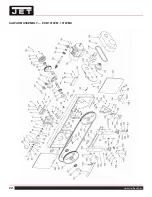
Страница 20: ...20 Horizontal Band Saw SAW ARM ASSEMBLY EHB 1018VM 1018VMH...

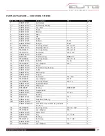
Страница 21: ...in 5 x 30 1 17 TS 0732061 Lock Washer 3 8 1 18 EHB916V 18 Driven 1 19 EHB916V 19 Thrust Bearing Housing 1 20 EHB916V 02 Collar 1 21 EHB916V 21 Disc Spring 6 22 EHB916V 22 Copper 1 23 TS 0267041 Set Sc...

Страница 22: ...w 3 16 x 3 8 2 75 EHB916V 75 Bracket 1 76 TS 0680031 Flat Washer 5 16 2 77 TS 0081031 Hex Cap Screw 5 16 x 3 4 2 78 TS 0081031 Hex Cap Screw 5 16 x 3 4 2 79 TS 0680031 Flat Washer 5 16 2 80 EHB916V 80...

Страница 23: ...8 16 1 1 4 2 131 TS 0267071 Set Screw 1 4 20 3 4 4 132 TS 0270061 Set Screw 5 16 18 5 8 1 133 EHB1018V 133 Bracket R H 4 134 EHB1018VM 134 Slide 1 134 1 EHB916V 134 1 Scale 1 135 EHB916V 135 Screw 3 1...

Страница 24: ...158 EHB916V 158 Special Knob 2 159 TS 0680041 Flat Washer 3 8 1 160 TS 0060031 Hex Head Screw 3 8 x 16 x 3 4 3 161 EHB1018V 161 Bracket 1 165 EHB916V 165 Round Head Screw 3 16 3 8 4 166 EHB916V 166 Co...

Страница 25: ...HB1018VM 308 4 Relay Socket 1 308 5 EHB1018VM 308 5 Terminal Block 9 308 6 EHB1018VM 308 6 Electrical Plate 1 308 7 EHB1018VM 308 7 Round Head Screw 3 16 x 3 8 54 308 8 TS 0680011 Washer 3 16 54 308 9...

Страница 26: ...1 308 5 EHB1018VM 308 5 Terminal Block 11 308 6 EHB1018VMH 308 6 Electrical Plate 1 308 7 EHB1018VM 308 7 Round Head Screw 3 16 x 3 8 62 308 8 TS 0680011 Washer 3 16 62 308 9 EHB1018VM 308 9 Power Cab...

Страница 27: ...LOT LAMP MAIN MOTOR U1 V1 W1 U2 V2 W2 TO HYDRAULIC K1 K3 U3 V3 W3 CS2 PB3 K1 K3 K1 10 9 6 SOL1 HYDRAULIC K2 PB1 PB4 PB2 PB4 19 K2 CS1 PB5 K3 COOLANT PUMP LS4 LS4 LS5 5 7 13 8 9 4 3 12 14 CR 21 OP 27 F...

Страница 28: ...LIGHT PILOT LAMP MAIN MOTOR UP DOWN U1 V1 W1 U2 V2 W2 TO HYDRAULIC K1 K2 U3 V3 W3 F1 F2 4 LS3 LS4 CS2 PB2 K1 1C 1C K1 19 10 9 5 7 PB5 SOL1 SOL2 K1 1C 14 15 1C PB6 PB7 PB6 PB7 17 18 SOL3 SOL4 K2 16 VI...

Страница 29: ...29 EHB 1018VM EHB 1018VMH NOTES...

Страница 30: ...30 Horizontal Band Saw NOTES...

Страница 31: ...31 EHB 1018VM EHB 1018VMH NOTES...

Страница 32: ...32 Horizontal Band Saw NOTES...

Отзывы: