background image


WIRING

CONNECTIONS

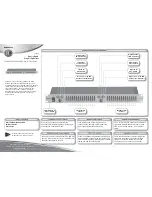
The wiring diagram depicts all the wiring connections required for proper 
operation of the unit.

The wiring diagram depicts all the wiring connections required for proper 
operation of the unit.

1

10

11

20

DETAIL A

PIN NO.

WIRE COLOR

GREY

GREY/BLACK

WHITE

WHITE/BLACK

BLACK

GREY (BLUE JACK)

BLACK

GREY (RED JACK)

BLACK

GREY (WHITE JACK)

VIOLET

VIOLET/BLACK

GREEN

GREEN/BLACK

RED

BLACK

BLACK

YELLOW (RED JACK)

BLACK

YELLOW (WHITE JACK)

10 

11 

12 

13 

14 

15 

16 

17 

18 

19 

20 

SHOWN FROM PIN VIEW

WARNING: 

Wiring harness comes with stripped and tinned leads to aid in the 

installation process. Any unused speaker wires must have their exposed ends cut 
off or insulated individually.


10AMP FUSE

5

AM/FM ANTENNA
SOCKET

WIRING HARNESS
CONNECTOR

JWM

20

DESCRIPTION

RIGHT(A) SPEAKER R+

RIGHT(A) SPEAKER R-

LEFT(A) SPEAKER L+

LEFT(A) SPEAKER L-

A-GROUND

SUBWOOFER

A-GROUND

LINE OUT R

A-GROUND

LINE OUT L

RIGHT(B) SPEAKER R+

RIGHT(B) SPEAKER R-

LEFT(B) SPEAKER L+

LEFT(B) SPEAKER L-

+12VDC SWITCHED

GROUND

A-GROUND

AUX IN R

A-GROUND

AUX IN L

IR REMOTE JACK

HDMI OUTPUT

Содержание JWM20

Страница 1: ...Installation and Owner s Manual JWM20 SLEEPALARM STEREO USB LOUD A B P SCAN STEREO USB L HDMI...

Страница 2: ...allation Wiring Connections Basic Operation Tuner Operation MP3 USB Operation Bluetooth Operation Remote Control Operation Care and Maintenance Troubleshooting Speci cations JWM20 3 4 5 5 6 8 9 10 12...

Страница 3: ...s to look through it you ll learn how to use all the features of your new Jensen receiver for maximum enjoyment Use the Proper Power Supply This product is designed to operate with a 12 volt DC negati...

Страница 4: ...r connections 16 18 gauge speaker wire Four M3x20mm 3 32 x 0 75 screws Places exposed to heat radiating appliances such as electric heaters Adjacent to other equipment that radiates heat Poorly ventil...

Страница 5: ...LOW WHITE JACK 2 3 4 5 6 7 8 9 10 11 12 13 14 15 16 17 18 19 20 SHOWN FROM PIN VIEW WARNING Wiring harness comes with stripped and tinned leads to aid in the installation process Any unused speaker wi...

Страница 6: ...temperature increases to a normal range JWM20 1 HDMI P SCAN 2 3 4 5 6 7 8 9 10 11 12 13 14 16 18 20 22 21 19 17 15 Liquid Crystal Display LCD The liquid crystal display LCD panel 10 displays the frequ...

Страница 7: ...our and minutes clock digit will ash Press the button 11 to adjust hour or press the button 12 to adjust minute USB Interface Connector Infrared receiver 1 is located on the bottom left of front panel...

Страница 8: ...matically Store Preset Scan AS PS Auto Store Select an AM or FM band Press hold the AM FM button 4 to access tuner menu list AUTO STORE PRESET SCAN Press AM FM button 4 repeatedly until AUTO STR appea...

Страница 9: ...hen USB is connected press BT USB button 5 repeatedly to enter USB playback mode direct Play Pause Press the button 22 to suspend or resume media playback Next Previous File Press the or buttons 12 11...

Страница 10: ...unit Select CONNECT for connection and Press button 22 to connect desired paired device LOCK UNLOCK The JWM20 can store up to 5 devices for Bluetooth connection The devices are stored in a FIFO First...

Страница 11: ...enter the Bluetooth mode Selecting Tracks During playback press or button 12 11 to play the previous or next track Pausing Playback During playback press button 22 to pause the Bluetooth audio playbac...

Страница 12: ...tations Silence Audio output Press and hold to turn LOUDNESS feature on off Silence Audio output Press and hold to turn LOUDNESS feature on off Select next previous track Select next previous track Fa...

Страница 13: ...system MENU Access system MENU Access Audio Menu options Access Audio Menu options Access Audio Menu options Select source for playback Select source for playback Select source for playback Switch Clo...

Страница 14: ...tage lines Although AM is subject to environmental noise it has the ability to receive at great distance This is because broadcasting signals follow the curvature of the earth and are re ected back by...

Страница 15: ...reception Unit does not respond to Remote Control Try the reset button Check fuse Check 12V on accessory wire to radio RED wire Check Ground Verify Volume Fader Balance Mute controls are set correctl...

Страница 16: ......

Отзывы: